6-6
Connecting TM I/O to PCS 7
C79000-G8076-C710-04
6.2.2 Grounding
For the operation of a PCS7/TM in the migration rack with TELEPERM M
I/O modules, the TELEPERM M Installation Guidelines in the Manual
“TELEPERM M, Notes and Guidelines on Planning, Installation and Opera-
tion”, Order No. C79000-G8076-C417 apply.
Information on grounding conception is found there in Chapter 7.2, as well as
in the “AS 235 User Manual”, Order No. C79000-G8076-C295, Operating
instructions C79000-B8076-C295, Chapter 4.2, 4.3 and 4.3.1.
According to DIN VDE 0150, Section. 3.2.1, multiple grounding of plants
with DC power supply is not allowed for reason of stray corrosion. For this
reason, migration systems must have only one galvanic connection between
local earth and M24. That is, although shielding and protective ground are
respectively connected to local earth via shielding busbar and cabinet groun-
ding bolt, chassis ground M24 is only connected to local earth at one point in
the system. That is, at the “Central Grounding Point“ - CGP - that applies to
all TELEPERM M systems of this plant.
According to “S7-400, M7-400 PLCs, Order No. C79000-G7076-C410”,
Chapter 4.6 and 4.7, the preassembled galvanic connection between M24 and
local earth related to the cabinet must be disconnected to establish a floating
potential assembly.
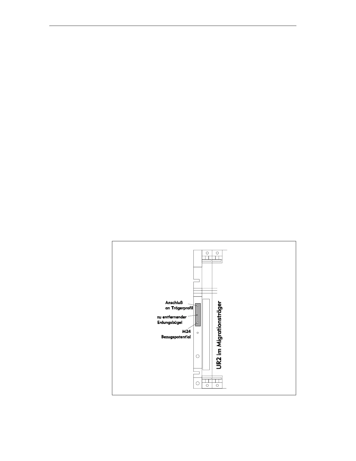
The grounding plate between M24 and local earth is located on the left side
of module rack UR2.
Figure 6-3 Grounding plate
Grounding
conception,
referencing
Protective earth
Grounding plate
Mi
ration rack II
 Loading...


