6-10
Connecting TM I/O to PCS 7
C79000-G8076-C710-04
6.4 Connector pin-out
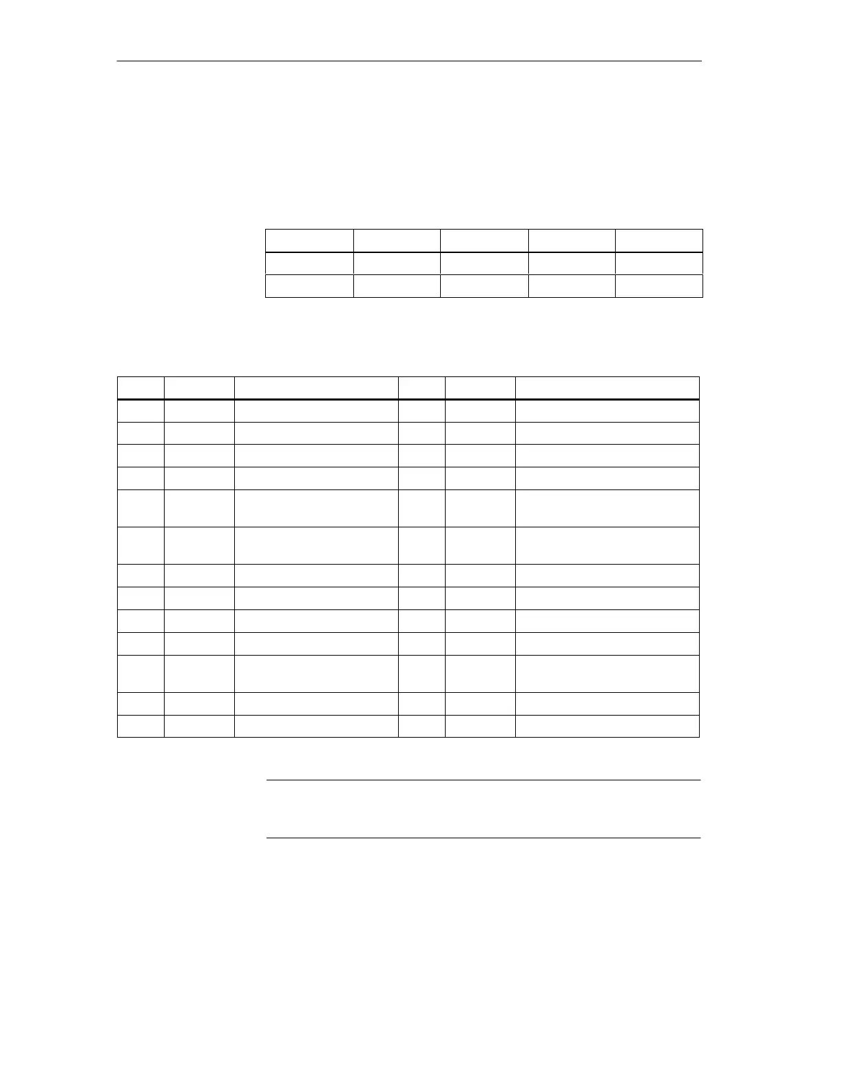
6.4.1 Pin-out 64-pole G-connector, all slots
Pin f d b z
30 nc BS PM MZ
32 L+ L+ M24 M24
6.4.2 Pin-out X30, 25-pole Sub-D connector, process control signals
Pin Signal Meaning Pin Signal Meaning
1 free 2 DO7 AM 3
3 DO6 Watchdog trigger 4 DO5 AM 2
5 DO4 AM 1 6 L+ = 24 VDC for DO 4...DO 7
7 M24 = M24 for DO 4...DO 7 8 DO3 Reserve message output
9 DO2 Message output for horn 10 DO1 PCM signal OUTPUT cabinet
lamp CL
11 DO0 Reserve message output 12 L+ =24 VDC load power supply for
DO 0...DO 3, fused
13 M24 = M24 for DO 0... DO 3 14 M24 = M24 for DI 0 and DI 1
15 DI0 Reserve message input 16 DI1 INPUT LK 1
17 M24 = M24 for DI 2, DI 3 18 DI2 INPUT Monitor T 1
19 DI3 INPUT TK 1 20 M24 = M24 for DI 4 and DI 5
21 DI4 Message input
Bus redundancy display
22 DI5 Horn acknowledgement
23 M24 = M for DI 6 and DI 7 24 DI6 EM 1
25 DI7 EM2
Signal image: see X31 ... X33, X35 ... X37 in Section 4.3
Note
Pins 6, 7, 12, 13, 14, 17, 20, 23 are pre-wired.
Mi
ration rack II
 Loading...


