6-9
Connecting TM I/O to PCS 7
C79000-G8076-C710-04
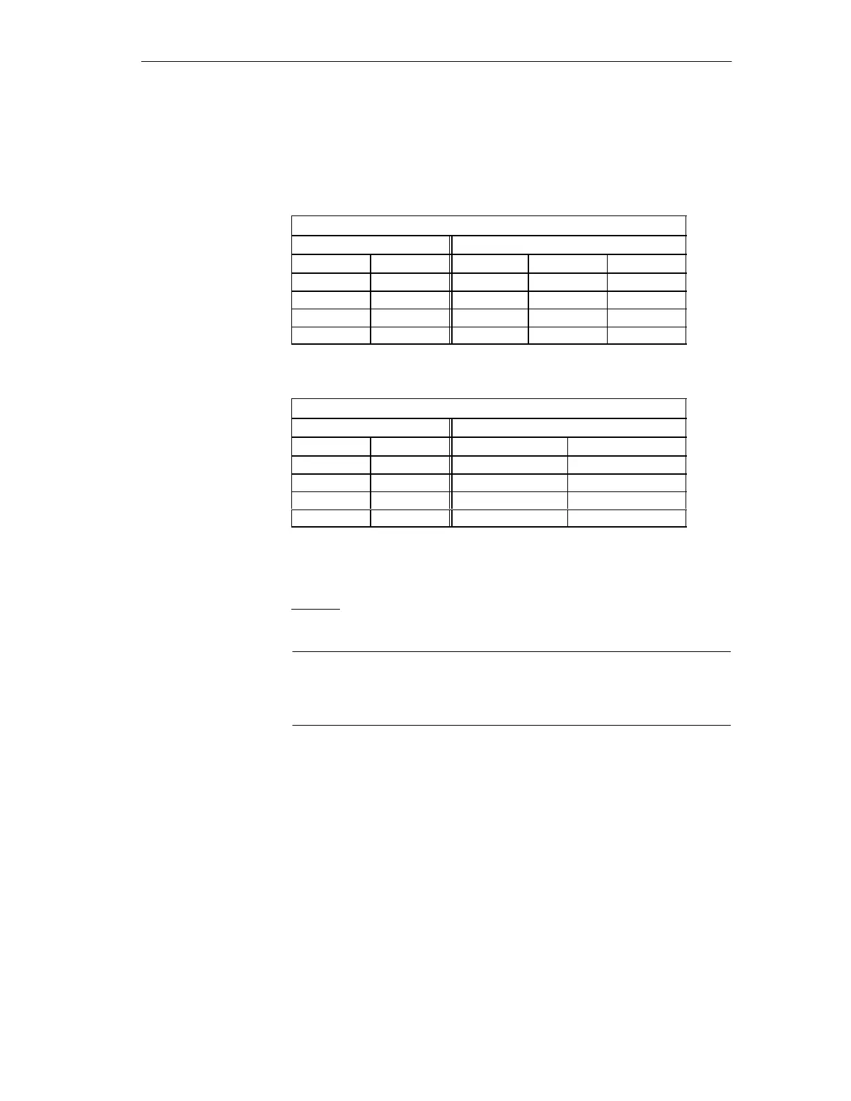
Two jumpers are available on every bus for setting the slot addresses for ope-
ration with TELEPERM-ME modules. The table below shows the respective
slot addresses.
These jumpers can also access from the front.
Bus A / Bus B
Position address Slot address
A10 A11 SL 1 SL2 SL3
x x 13/113 14/114 15/115
0 x 29/129 30/130 31/131
x 0 45/145 46/146 47/147
0 0 61/161 (62/162) (63/163)
BUS A / Bus B
Position address Slot address
A10 A11 SL 4 SL5
x x 14/114 15/115
0 x 30/130 31/131
x 0 45/145 46/146
0 0 (62/162) (63/163)
x = Jumper inserted
0 = Jumper not inserted
(62/162) = unusable or impermissible combination,
SL can be used with bridge addresses.
Caution
Depending on the setting, you might create slots with the same slot address.
Double addressing must be prevented with an appropriate configuration.
Slot addresses
Mi
ration rack II