Technical specifications
A.3 Fail-Safe signal module (SM) technical specifications
S7-1200 Functional Safety Manual
Manual, 02/2015, A5E03470344-AA
179
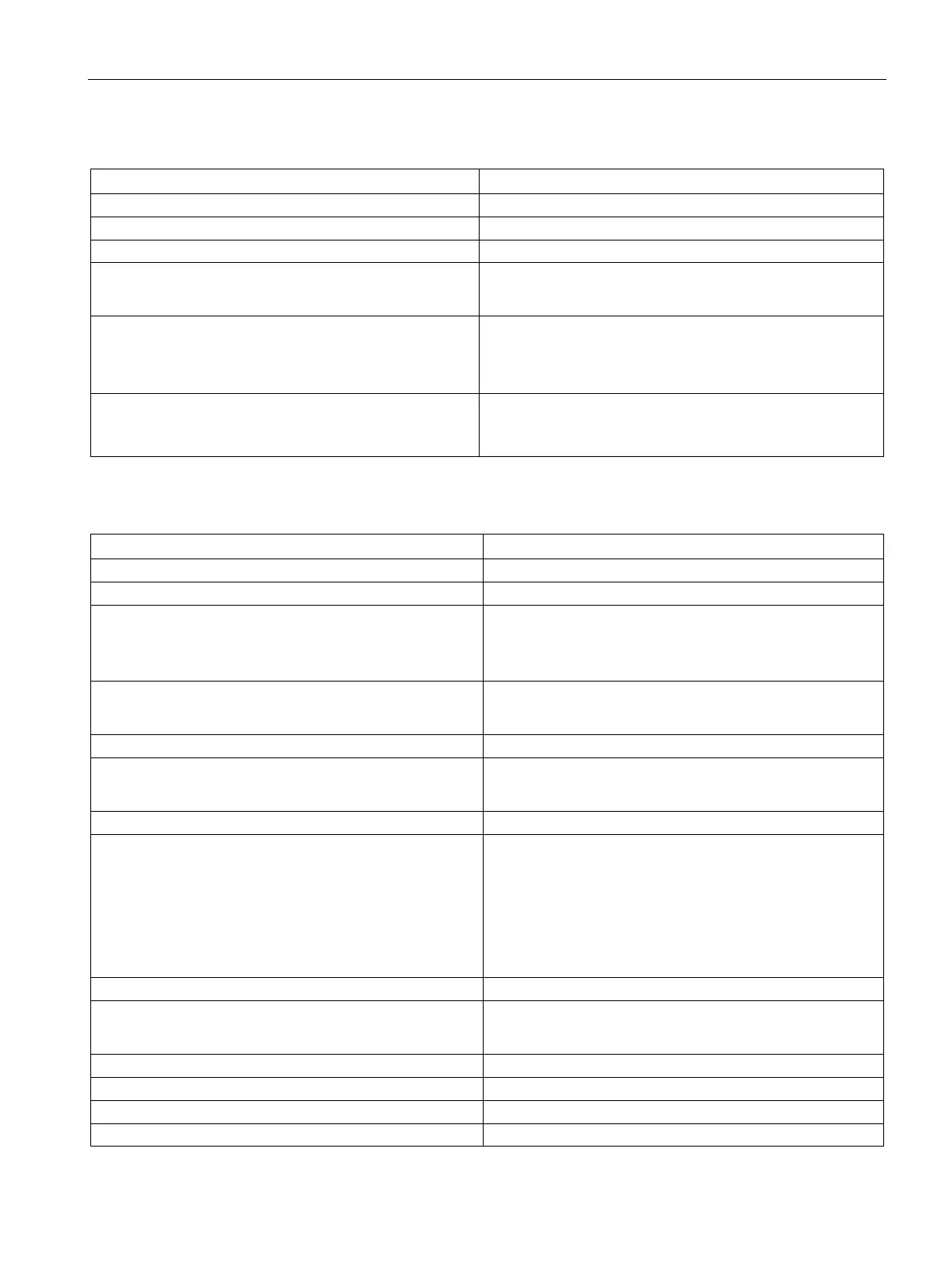
Table A- 55 Power supply (L+, M)
Surge voltage 35 VDC for 0.5 s
170 mA (does not include current in all P-switch loads)
Hold up time (loss of power)
• None for outputs
• 1.0 ms at 20.4 VDC for internal power
Internal fuse, not replaceable
• 1 A for logic power
• 7 A common for P-switch outputs F-DQ a.0 and F-DQ a.1
• 7 A common for P-switch outputs F-DQ a.2 and F-DQ a.3
Reverse polarity protection Yes
Note: Refer to "Reverse polarity protection" in the SM 1226
F-DQ 4 x 24 VDC "Digital outputs" table for more information.
Table A- 56 Digital outputs
Logic 1 signal at maximum current L+ minus 2.0 VDC (minimum):
• P-switch: L+ minus 1.5 VDC (maximum)
• M-switch: 0.5 VDC (maximum)
Logic 1 current
• 2 A nominal
• 10 mA to 2.4 A
Logic 0 current (residual)
• P-switch: 0.5 mA, maximum
• M-switch: 0.5 mA, maximum
Output overload protection:
• M-switch
• P-switch
Yes, electronic in addition to internal non-replaceable fuse.
Threshold of 25 A to 45 A turns M-switch OFF.
Threshold of 2.4 A to 3.8 A, 400 ms time constant filter,
measured at P-switch, turns both switches OFF.
7 A fuse can open for large faults.
Note: Refer to "Fuse and electronic overload protection"
(Page 180) for more information.
Current per common (maximum)
Inductive clamp voltage
• M-switch: + 48 VDC referenced to M
• P-switch: - 26 VDC referenced to M
Number of outputs on simultaneously
4 at 55 °C horizontal or 45 °C vertical
Parallel connection of 2 outputs
Control of a digital input

 Loading...


