Technical specifications
A.3 Fail-Safe signal module (SM) technical specifications
S7-1200 Functional Safety Manual
188 Manual, 02/2015, A5E03470344-AA
Adjacent relay contacts in the same channel of the SM 1226 F DQ 2 x Relay are not rated
to separate AC line from SELV / PELV.
Death or serious personal injury and damage to machines and equipment may result if
SELV/PELV circuits are wired adjacent to high voltage circuits on this module.
The A and B circuits of each output must either be both AC line or both SELV.
Switching performance and service life of contacts
Note the "Switching performance and service life of contacts" table below. You should equip
Inductive loads with suppression circuits to avoid shortened relay contact life and to avoid
excessive switching noise. Refer to "Guidelines for inductive loads" (Page 101) for more
information:
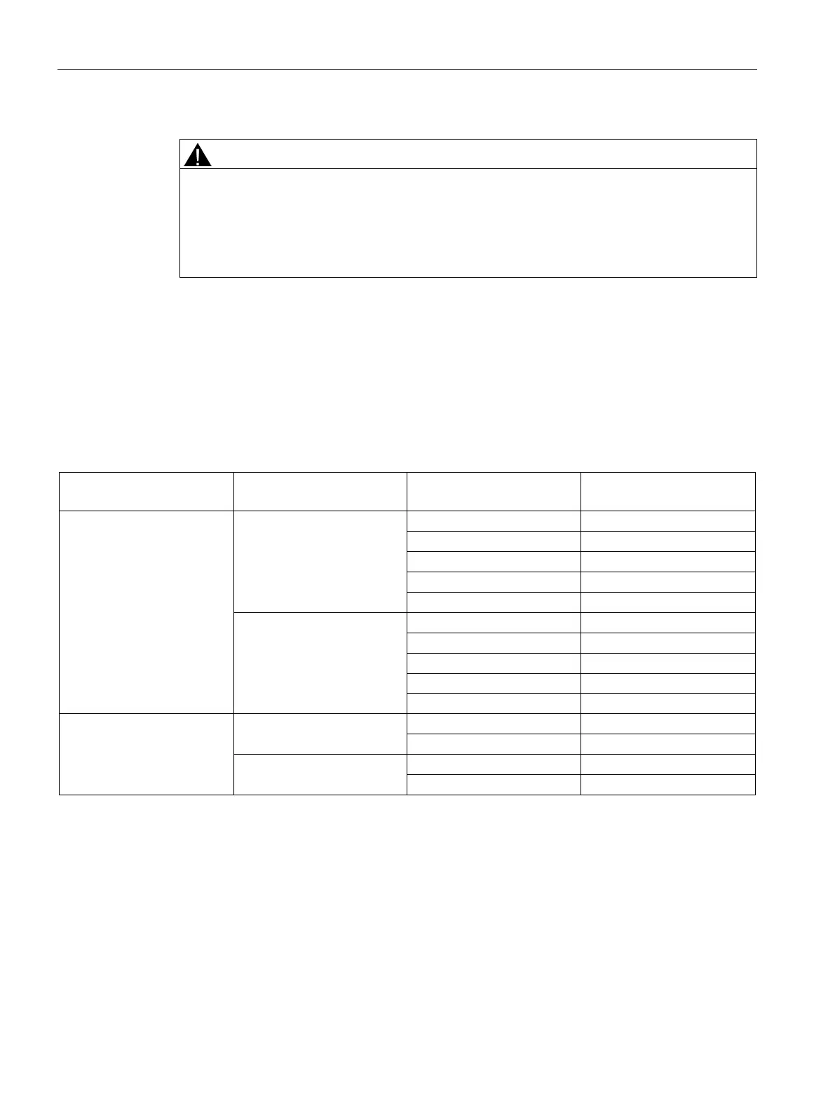
Table A- 63 Switching performance and service life of contacts
Duty cycle (typical) Normally-
Open (NO) contact
For resistive load 24 VDC
230 VAC
2.0 A 0.2 million
0.5 A 0.8 million
For inductive load to IEC
60947-5-1 DC13/AC15
24 VDC
230 VAC

 Loading...


