Technical specifications
A.3 Fail-Safe signal module (SM) technical specifications
S7-1200 Functional Safety Manual
186 Manual, 02/2015, A5E03470344-AA
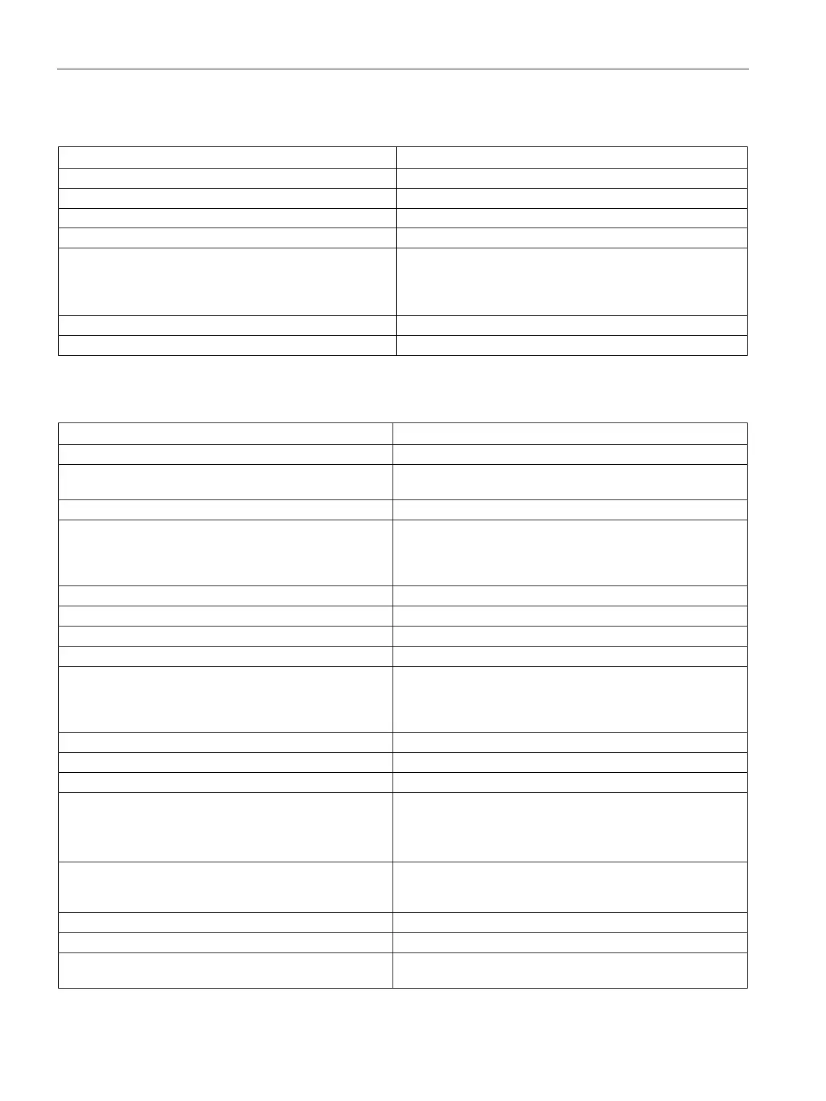
Table A- 61 Power supply (L+, M)
Surge voltage 35 VDC for 0.5 s
Isolation (L+, M to S7-1200 internal logic and Ground) 500 VAC for 1 min
Hold up time (loss of power)
• None for outputs
• 1.0 ms at 20.4 VDC for internal power with outputs off
• 0.5 ms at 20.4 VDC with either output or both outputs on
Internal fuse, not user replaceable 1 A for internal power
Reverse polarity protection
Table A- 62 Digital outputs
2 (2 circuits per output)
Type Relay, mechanically linked sense contact monitored internal
5 to 30 VDC or 5 to 250 VAC
Output current:
• Continuous thermal current
• Minimum load current
5 A maximum per circuit
5 mA
Current per module (maximum) – all output circuits
10A at 55 °C horizontal or 45 °C vertical
ON state contact resistance
Short-circuit protection of output None; external fuse or circuit breaker required. General pur-
pose fuse type gG per IEC 60269, 5A maximum on each
circuit.
Some application standards require derating.
Overload protection of output
Isolation (output circuits to logic)
2200 VAC for 1 min, rated for Overvoltage Category III
Isolation (output circuits to power supply)
2200 VAC for 1 min, rated for Overvoltage Category III
Isolation (circuit to circuit on same output) 2200 VAC for 1 min
Note : Circuit-to-circuit isolation (A circuit to B circuit) on the
same output is not rated to separate line voltage from SELV /
Isolation (output to output) 2200 VAC for 1 min; rated for Overvoltage Category III, in-
cluding Overvoltage Category III to SELV separation or differ-
None; external protection required.
On delay time Typically 20 ms to both series contacts closed, including 8 ms
separation between commands to series contacts

 Loading...


