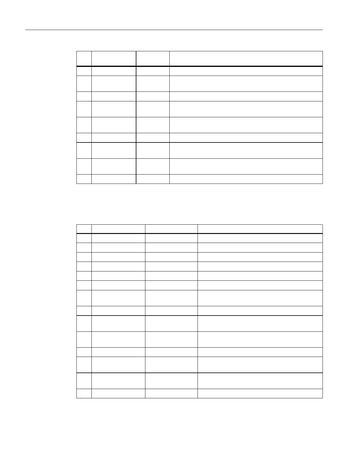
Pin Designation
1)
Signal type
2)
Notes
6 DI17 I Digital input 17
7 M1 GND Ground for DI0 to DI3, DI16, DI17
(isolated from M)
8 M GND Ground
9 DI/DQ8 B Digital input/output 8
(also usable as measurement sensing input)
10 DI/DQ9 B Digital input/output 9
(also usable as measurement sensing input)
11 M GND Ground
12 DI/DQ10 B Digital input/output 10
(also usable as measurement sensing input)
13 DI/DQ11 B Digital input/output 11
(also usable as measurement sensing input)
14 M GND Ground
1)
DI: Digital input; DI/DQ: Bidirectional digital input/output; M: Electronic ground;
M1: Ground reference
2)
B = Bidirectional; I = Input; GND = Reference potential (ground)
Table 4-8Digital inputs and digital inputs/outputs of X132
Pin Designation
1)
Signal type
2)
Notes
1 DI4 I Digital input 4
2 DI5 I Digital input 5
3 DI6 I Digital input 6
4 DI7 I Digital input 7
5 DI20 I Digital input 20
6 DI21 I Digital input 21
7 M2 GND Ground for DI4 to DI7, DI20, DI21
(isolated from M)
8 M GND Ground
9 DI/DQ12 B Digital input/output 12
(also usable as measurement sensing input)
10 DI/DQ13 B Digital input/output 13
(also usable as measurement sensing input)
11 M GND Ground
12 DI/DQ14 B Digital input/output 14
(also usable as measurement sensing input)
13 DI/DQ15 B Digital input/output 15
(also usable as measurement sensing input)
14 M GND Ground
1)
DI: Digital input; DI/DQ: Bidirectional digital input/output; M: Electronic ground;
M2: Ground reference
2)
B = Bidirectional; I = Input; GND = Reference potential (ground)
50
SIMATIC Drive Controller
Equipment Manual, 11/2022, A5E46600370-AC
Connecting
4.4 Digital inputs and outputs of X122, X132 and X142

 Loading...


