NOTE
Open input of digital inputs
An open input is interpreted as "low".
So that the digital inputs will function, connect terminalM1 or M2. The alternatives are as
follows:
• Connect the coupled reference ground of the digital inputs to M1 or M2.
• Connect a jumper to terminalM and terminalM1 (or between M and M2). This removes
the electrical isolation for these digital inputs.
The interfaces of the onboard I/O are described in section Digital inputs and outputs of X122,
X132 and X142 (Page 48).
4.6.3 DRIVE-CLiQ interfaces X100 to X103
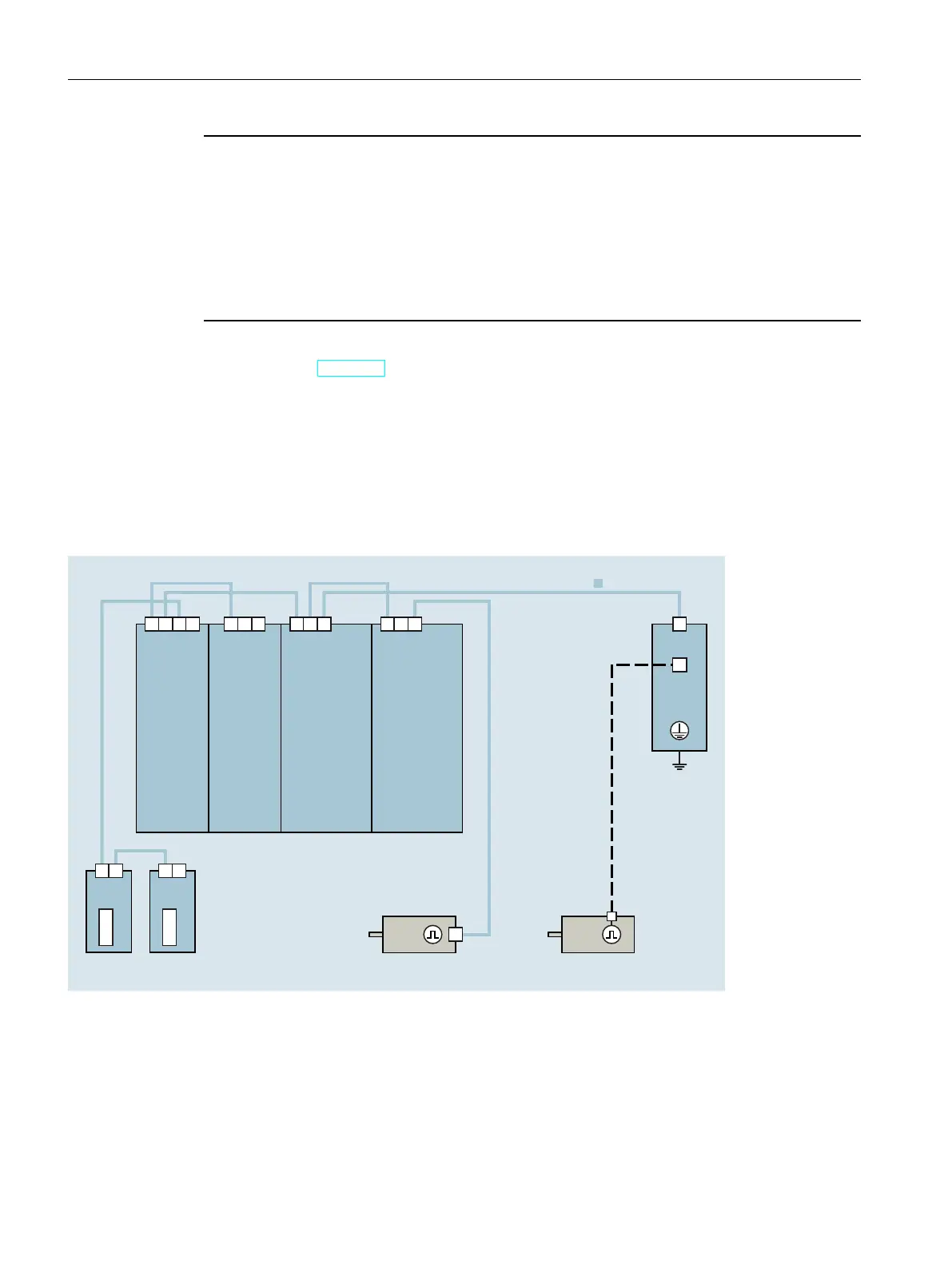
DRIVE-CLiQ wiring of an axis group
The figure below shows a possible DRIVE‑CLiQ wiring of an axis group.
6,0$7,&
'ULYH&RQWUROOHU
$FWLYH
/LQH
0RGXOH
6LQJOH
0RWRU
0RGXOH
6LQJOH
0RWRU
0RGXOH
6SHHG
5RWRUSRVLWLRQ
7HPSHUDWXUH
0RWRU0RWRU
'5,9(&/L4
60&[[
;;;;;;
;;
70[[
70[[
;
;
;
;
;
;
Figure 4-4Example of a DRIVE‑CLiQ wiring of an axis group
Wiring rules
Neither ring wiring nor double wiring of components is permitted in the DRIVE-CLiQ wiring. In
the case of a Motor Module, you must connect the power cable to the motor and the
associated encoder.
56
SIMATIC Drive Controller
Equipment Manual, 11/2022, A5E46600370-AC
Connecting
4.6 Wiring and block diagrams

 Loading...


