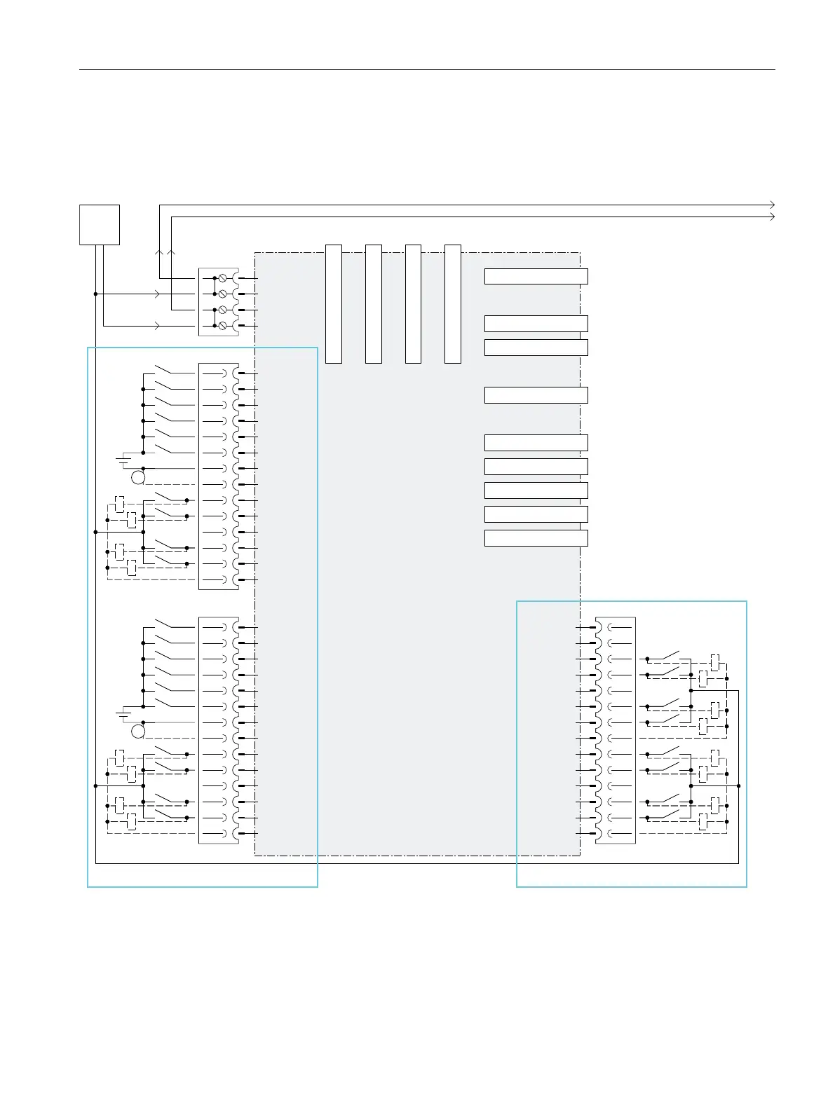
4.6.2 Onboard digital inputs/digital outputs of X122, X132 and X142
The figure below shows the wiring and block diagram of the digital inputs and digital
inputs/outputs of the SIMATIC Drive Controller.
1
1
'5,9(&/L4VRFNHW
'5,9(&/L4VRFNHW
'5,9(&/L4VRFNHW
'5,9(&/L4VRFNHW
([W
b9
6'PHPRU\FDUG
5HVHUYHG
5HVHUYHG
;
;
;;
0
0
0
352),1(7,2,57
352),1(7,2,57
352),1(7,2,57
352),1(7
352),1(7,257
86%
86%
;;
;
352),%86'3
6,1$0,&6,2
&38,2
;
;35
;35
;3
;3
;3
;
;
0
;
;
;
9
0
0
',
',
',
',
',
',
0
0
0
0
','4
','4
','4
','4
',
',
',
',
',
',
0
0
0
0
','4
','4
','4
','4
0
0
0
0
','4
','4
','4
','4
','4
','4
','4
','4
① Connection removes electrical isolation
Figure 4-3Wiring and block diagram of onboard digital inputs and digital inputs/outputs
55
Connecting
4.6 Wiring and block diagrams
SIMATIC Drive Controller
Equipment Manual, 11/2022, A5E46600370-AC

 Loading...


