2. Creating R1 devices
In the example, you add two R1 devices with system redundancy R1 to the H-CPUs. To do so,
proceed as follows:
1.
Switch to the network view.
2.
Drag an ET 200SP IM 155-6 PN R1 from the hardware catalog into the working window.
3.
Switch to the device view of the ET 200SP IM 155-6 PN R1.
4.
Drag the desired I/O modules and the server module to the respective slots of the ET
200SP IM 155-6 PN R1.
5.
Repeat steps 1 to 4 for the second ET 200SP IM 155-6 PN R1.
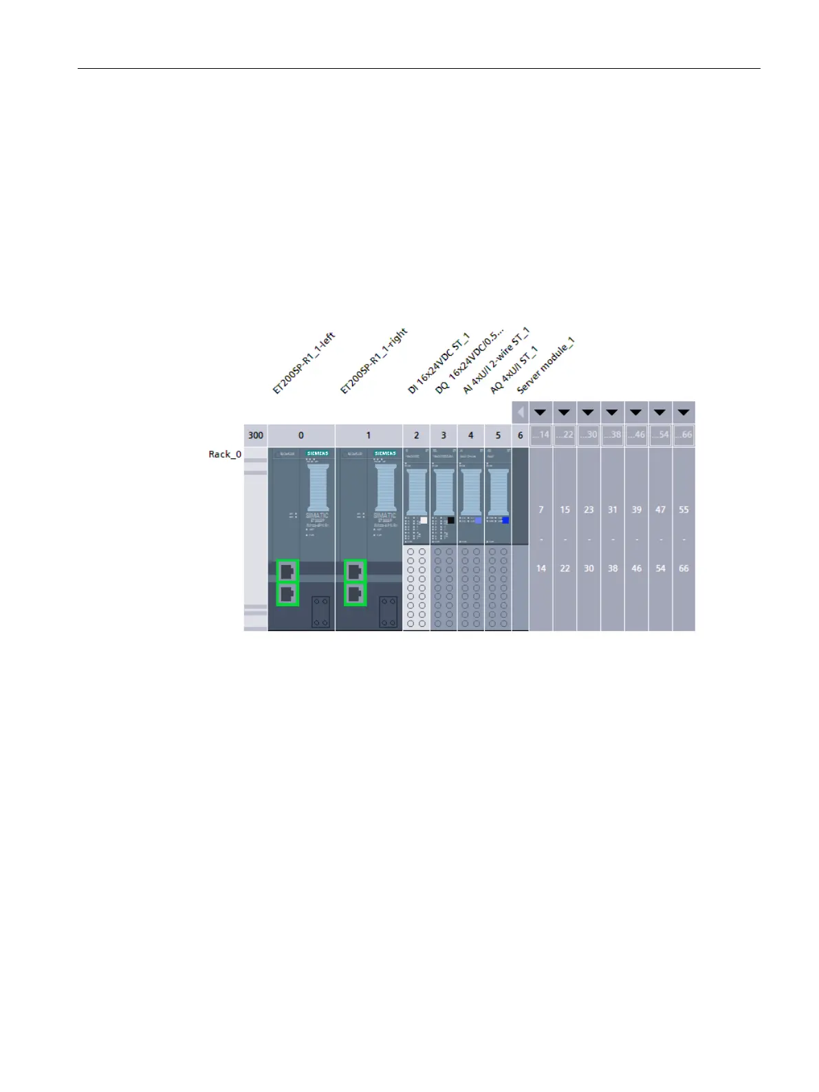
Result: The R1 devices are created and the modules are assigned.
Figure 8-9ET 200SP IM 155-6 PN R1 created and modules assigned
3. Assigning IO devices to the redundant system
To assign R1 devices to the redundant S7-1500H system, connect each interface module of
the R1 device to each H-CPU.
The left interface module of each R1 device must be connected to the left H-CPU in the
network view. The right interface module of each R1 device must be connected to the right
H-CPU in the network view.
To do so, proceed as follows:
1.
Switch to the network view.
2.
Drag-and-drop a line between the PROFINET interface of the left interface module of the
ET200SP-R1_1 station and the PROFINET interface X1 of the left H-CPU.
3.
Drag-and-drop a line between the PROFINET interface of the right interface module of the
ET200SP-R1_1 station and the PROFINET interface X1 of the right H-CPU.
205
Configuration
8.4 Configuring H-CPUs with PROFINET rings and R1 devices
S7-1500R/H redundant system
System Manual, 11/2022, A5E41814787-AD
 Loading...


