Parameter data records
B.3 Structure of a data record for output channels of the analog on-board I/O
CPU 1512C-1 PN (6ES7512-1CK00-0AB0)
Manual, 09/2016, A5E35306440-AB
157
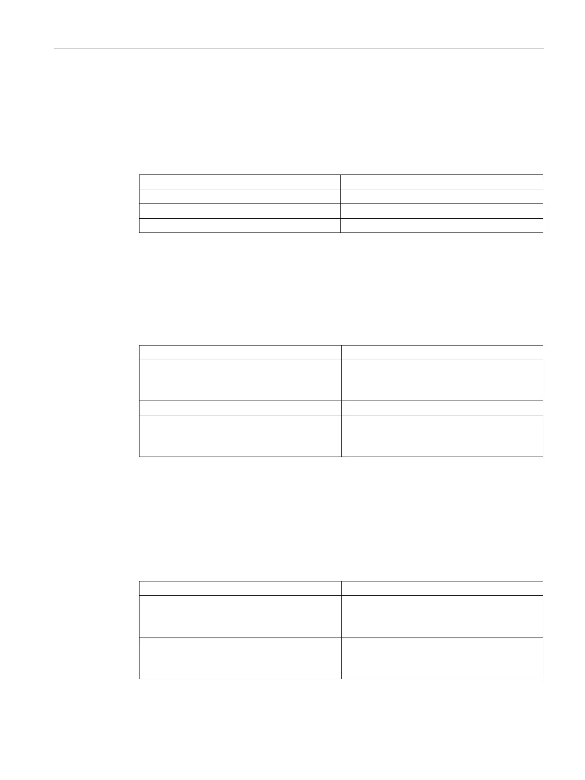
The following table contains all output types of the outputs of the analog on-board I/O with
the corresponding codes. You must enter these codes in each case in byte 2 of the data
record for the corresponding channel (see the previous figure).
Table B- 8 Codes for the output type
Voltage 0000 0001
The following table contains all output ranges for voltage and current of the outputs of the
analog on-board I/O with the corresponding codes. You must enter these codes in each case
in byte 3 of the corresponding data record (see previous figure).
Table B- 9 Codes for output range
1 to 5 V
0 to 10 V
0000 0011
0000 0010
0 to 20 mA
4 to 20 mA
0000 0001
0000 0010
Permitted substitute values
The following table lists all output ranges for the permitted substitute values. You must enter
these substitute values in each case in bytes 6 and 7 of the data record for the
corresponding channel (see the previous figure). You can find the binary representation of
the output ranges in the section Representation of output ranges (Page 185).
Table B- 10 Permitted substitute value for the output range
Permitted substitute value
±10 V
1 to 5 V
-32512 ... +32511
-6912 ... +32511
±20 mA
4 to 20 mA
-32512 ... +32511
-6912 ... +32511
 Loading...


