EasyManuals Logo

Siemens SIMATIC S7-1500T User Manual

Siemens SIMATIC S7-1500T
188 pages
To Next Page IconTo Next Page
To Previous Page IconTo Previous Page
Page #79 background imageLoading...
Page #79 background image
Wiring
4.3 Terminal and block diagrams
CPU 1512C-1 PN (6ES7512-1CK00-0AB0)
Manual, 09/2016, A5E35306440-AB
79
Wiring: Voltage output
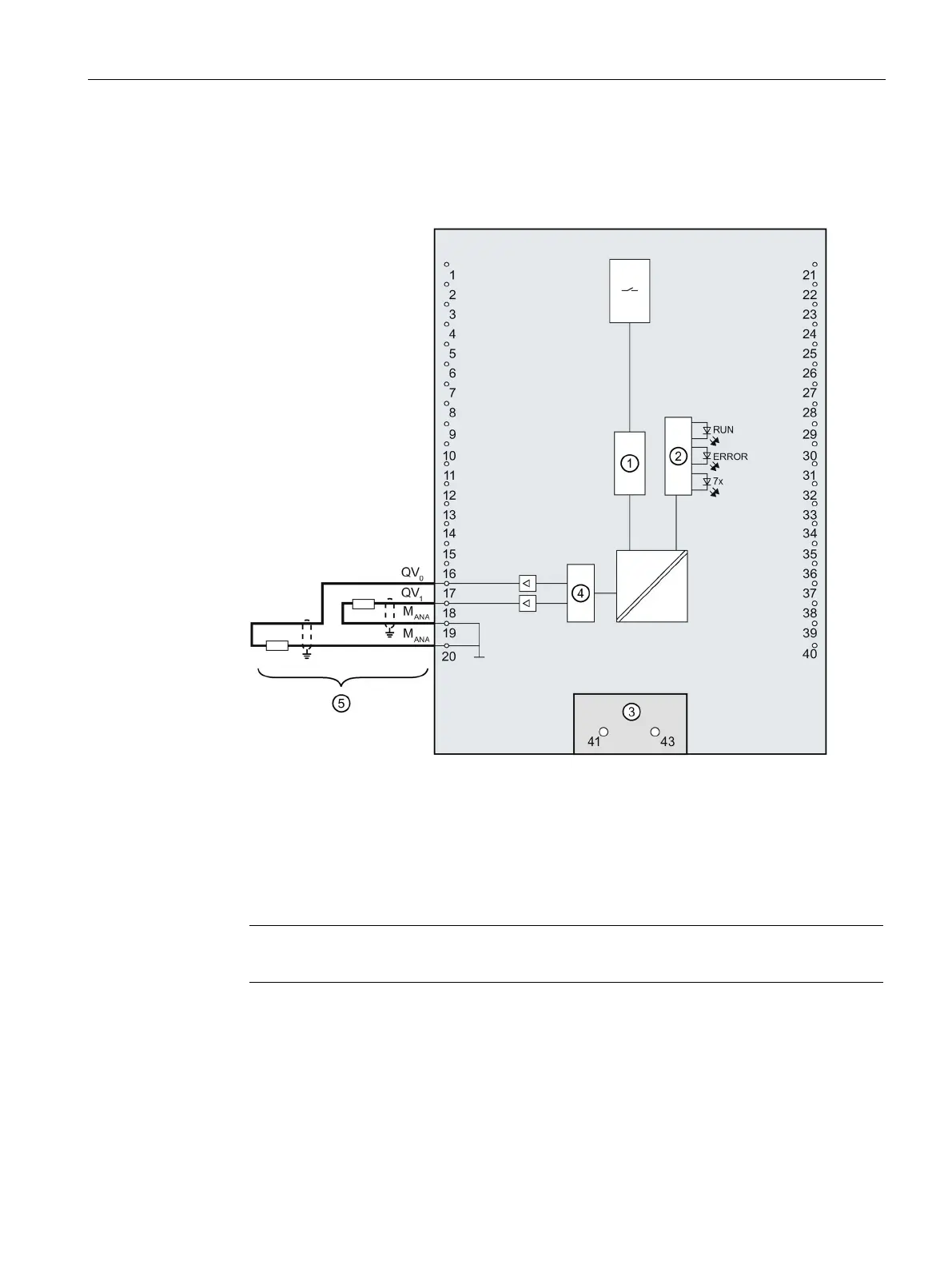
The figure below shows the terminal assignment for the wiring of the voltage outputs with:
2-wire connection, no compensation for line resistances.
Analog-to-digital converter (ADC)
LED interface
Infeed element (for shielding only)
Digital-to-analog converter (DAC)
2-wire connection CH0 and CH1
Figure 4-9 Block diagram and terminal assignment for voltage output
Note
M
ANA
on terminals 19 and 20 is equivalent.

Table of Contents

Other manuals for Siemens SIMATIC S7-1500T

Questions and Answers:

Question and Answer IconNeed help?

Do you have a question about the Siemens SIMATIC S7-1500T and is the answer not in the manual?

Siemens SIMATIC S7-1500T Specifications

General IconGeneral
BrandSiemens
ModelSIMATIC S7-1500T
CategoryController
LanguageEnglish

Related product manuals