Time switch based on the S7-300/400 CPUs with simple HMI system
including radio-controlled clock connection
Rev. B - final 19.07.2002 28/84
Copyright © Siemens AG 2005 All rights reserved
BID21669756_Zeitschaltuhr_einfach_DOKU_v20_e.doc
4 Examples of Function Mechanisms
4.1 Introduction
What will you find here?
Every hardware, standard and user software component is examined
separately and their functions described.
What can you do with it?
The example contains some (partial) solutions around the “time switching in
the S7” subject. With minor adjustments you can use them as the basis for
your own requirements.
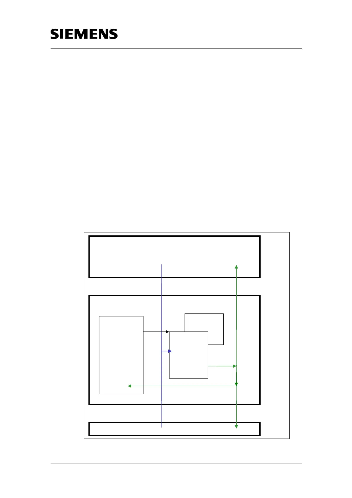
4.2 Overview of the Structure Elements
Figure 4-1 illustrates all function units of this application. They are
described one by one in the following chapters.
Chapt. 4.4
Chapt. 4.3
Process
S7-CPU
OB1/TimeOB
Call of the resp. FB
with the respective
Instance DB, call o
further blocks for
program procedure
“Time function“
Input parameter
Output parameter
Data interface
in Instance DB
HMI Unit
User interface
connected via
Program
further processed
feeds back
calls
displayed
Fig. 4-1 Structural layout of the application

 Loading...


