EasyManuals Logo

Siemens Simatic S7-400 Application Description

Siemens Simatic S7-400
84 pages
To Next Page IconTo Next Page
To Previous Page IconTo Previous Page
Page #73 background imageLoading...
Page #73 background image
Time switch based on the S7-300/400 CPUs with simple HMI system
including radio-controlled clock connection
Rev. B - final 19.07.2002 73/84
Copyright © Siemens AG 2005 All rights reserved
BID21669756_Zeitschaltuhr_einfach_DOKU_v20_e.doc
7.2 Relative time switch
For the relative time switch (FB124) the correct evaluation of the individual
inputs is important. Depending on whether the clock will be active, whether
the time to elapse restarts at every edge or only at the first edge.
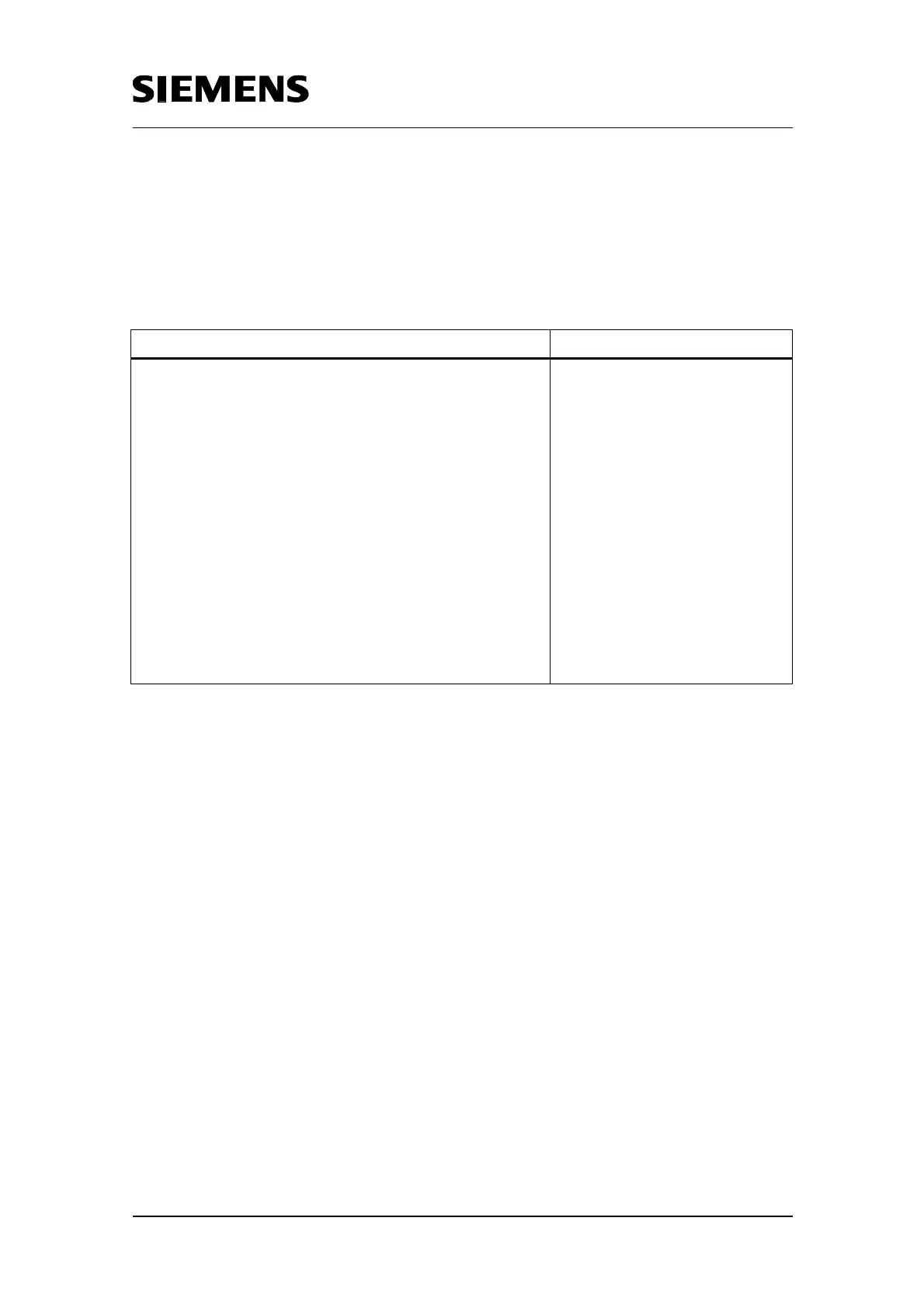
Table 7-3 Code relative time switch
Code Remarks
NETWORK 1:
L 0
T #err
UN #start
SPB next
UN #checkflank
SPB n2
SPA flan
n2: NOP 0
U #Q
SPB next
flan: NOP 0
U #enable
FP #startenable
= #impuls
UN #impuls
SPB next
Clock not enabled-> check
whether still active and needs to
be switched off
Only the first edge is reacted to
If output still active -> reset
output, otherwise
check whether new positive edge
at the input “Enable“

Table of Contents

Other manuals for Siemens Simatic S7-400

Questions and Answers:

Question and Answer IconNeed help?

Do you have a question about the Siemens Simatic S7-400 and is the answer not in the manual?

Siemens Simatic S7-400 Specifications

General IconGeneral
Programming LanguageSTEP 7 (LAD, FBD, STL, SCL, GRAPH)
Communication InterfacesMPI, PROFIBUS
Power Supply24 V DC, 120/230 V AC (Power supply modules are separate and chosen based on system requirements)
Operating Temperature0°C to 60°C
MountingRack mounting
ProcessorCPU 412-1, CPU 414-2, CPU 416-2, CPU 417-4 (Different CPUs offer varying performance and features)
Relative Humidity5 to 95% (non-condensing)

Related product manuals