Cycle and Response Times of the S7-400
9.5 Reaction Time
S7-400 Automation System, CPU Specifications
9-14 Manual, 10/2006, 6ES7498-8AA04-8BA0
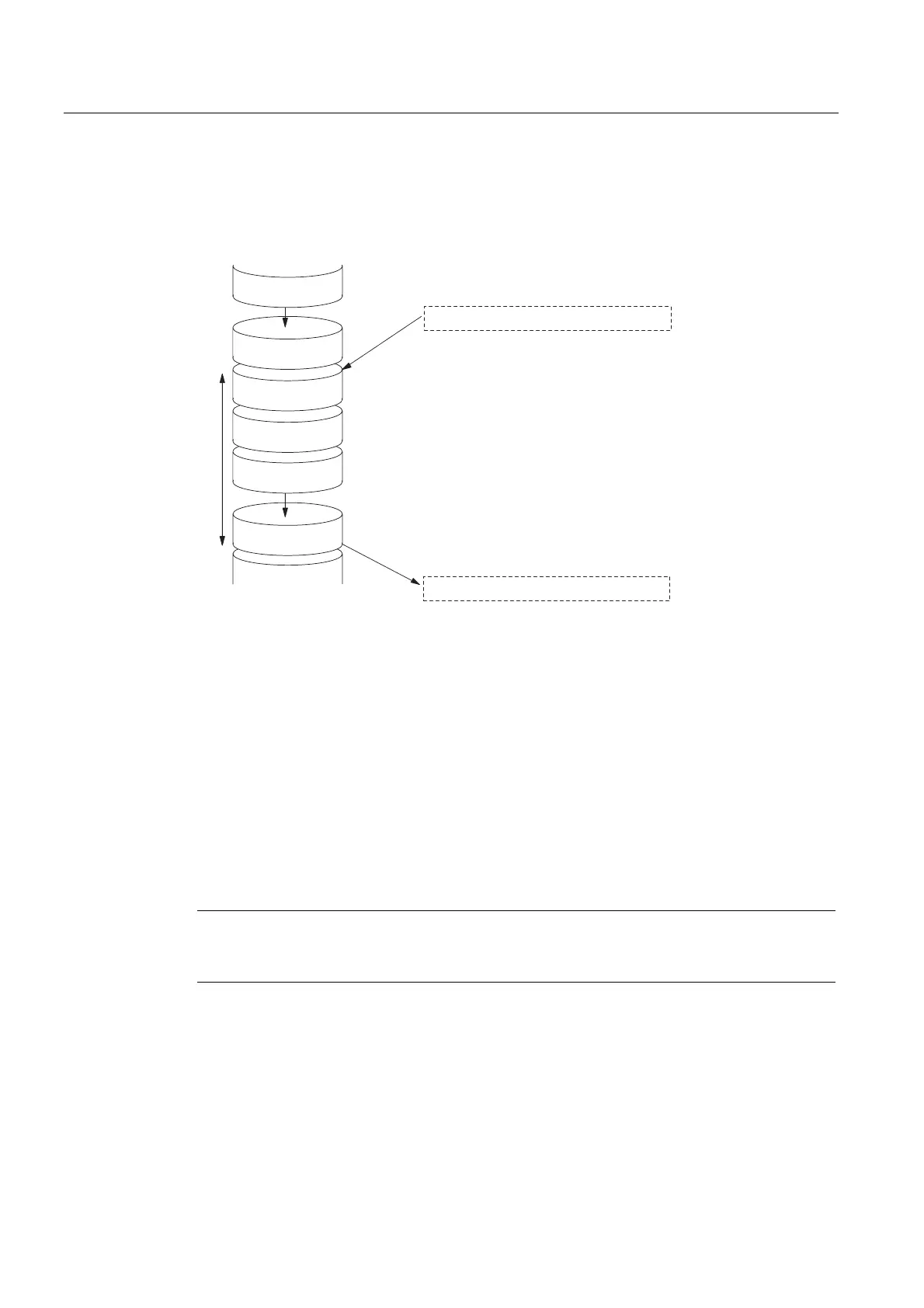
Shortest Response Time
The following figure illustrates the conditions under which the shortest response time can be
achieved.
SCC (OS)
PII
PIQ
PIQ
SCC (OS)
Delay in the inputs
Immediately before the PII is read in, the status of the input under
review changes. The change of input signal is also taken into
account in the PII.
The change of input signal is processed here by the user program.
The reaction of the user program to the change of input signal is
output here to the outputs.
Delay in the outputs
Reaction Time
User
program
Figure 9-9 Shortest response time
Calculation
The (shortest) response time is made up as follows:
● 1 x process image transfer time for the inputs +
● 1 x process image transfer time for the outputs +
● 1 x program processing time +
● 1 × operating system processing time at the SCC +
● Delay in the inputs and outputs
The result is equivalent to the sum of the cycle time plus the I/O delay times.
Note
If the CPU and signal module are not in the central rack, you have to add double the runtime
of the DP slave frame (including processing in the DP master).

 Loading...


