Cycle and Response Times of the S7-400
9.5 Reaction Time
S7-400 Automation System, CPU Specifications
Manual, 10/2006, 6ES7498-8AA04-8BA0
9-15
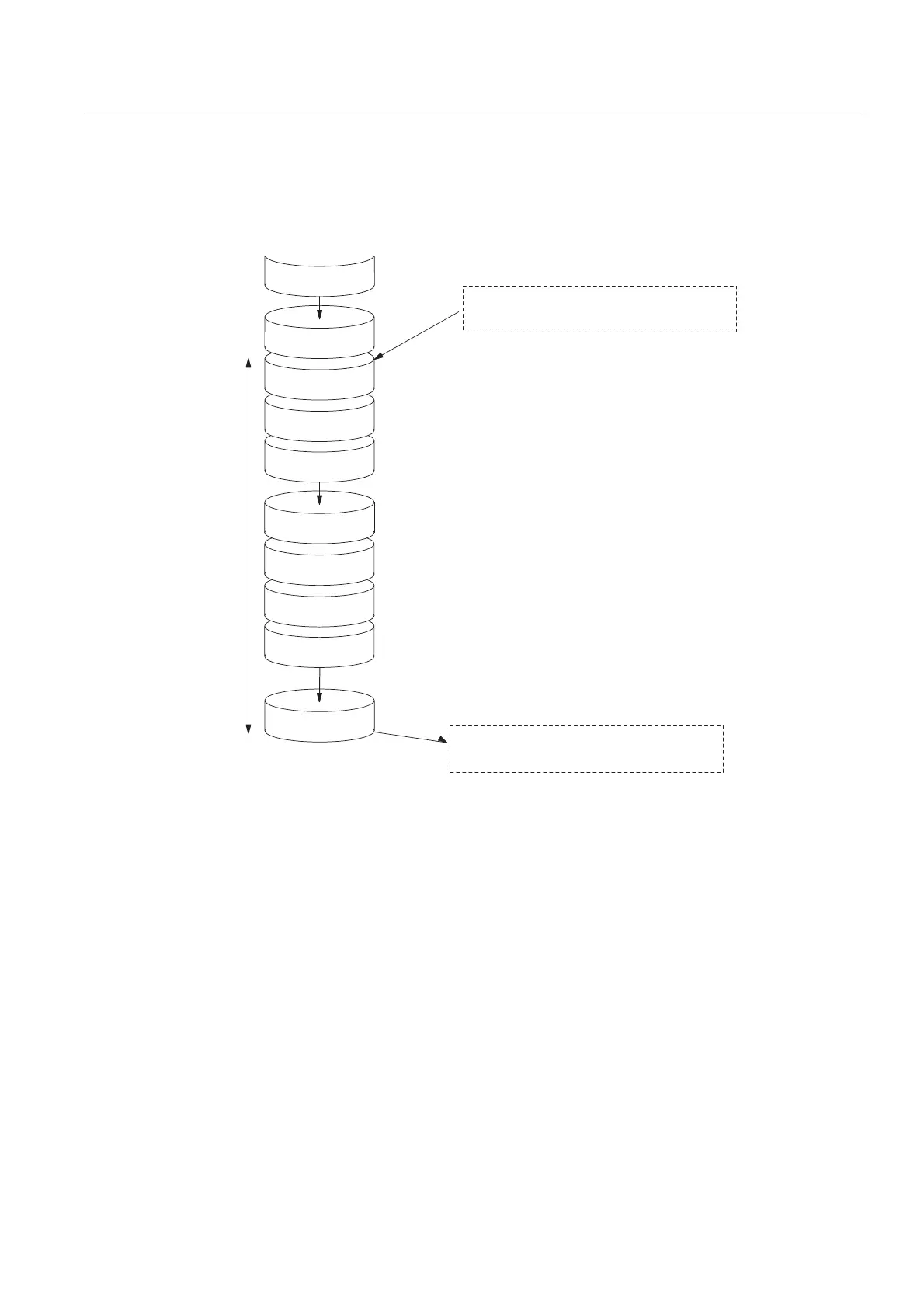
Longest Response Time
The following figure shows you how the longest response time results.
SCC (OS)
PII
PIQ
PIQ
SCC (OS)
SCC (OS)
PII
PIQ
Reaction Time
User
program
User
program
While the PII is being read in, the status of the input under
review changes. The change of input signal is no longer taken
into account in the PII.
The change of input signal is processed here by the user
program.
The reaction of the user program to the change of input signal
is output here to the outputs.
Here the change of input signal is taken into account in the
PII.
Delay in the inputs
+DP cycle time on PROFIBUS-DP
Delay in the outputs
+DP cycle time on PROFIBUS-DP
Figure 9-10 Longest response time
Calculation
The (longest) response time is made up as follows:
● 2 x process image transfer time for the inputs +
● 2 x process image transfer time for the outputs +
● 2 × operating system processing time +
● 2 x program processing time +
● 2 x runtime of the DP slave frame (including processing in the DP master) +
● Delay in the inputs and outputs
This is equivalent to the sum of twice the cycle time and the delay in the inputs and outputs
plus twice the DP cycle time.

 Loading...


