PROFIBUS DP
5.1 CPU 41x-3 PN/DP as DP master / DP slave
S7-400 Automation System, CPU Specifications
5-12 Manual, 10/2006, 6ES7498-8AA04-8BA0
Data Transfer Via an Transfer Memory
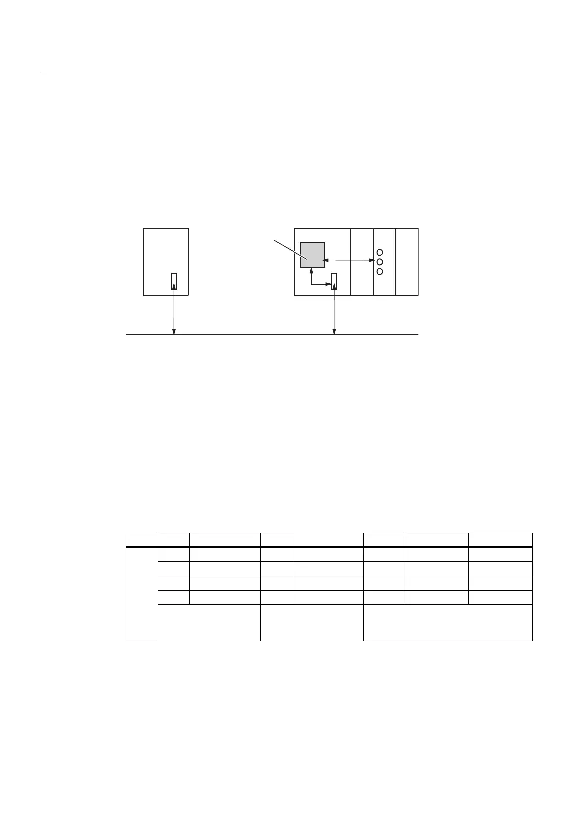
As a DP slave the CPU 41x makes an transfer memory available to PROFIBUS DP. Data
transfer between the CPU as DP slave and the DP master always takes place via this
transfer memory. Configure the following address areas: 244 bytes per input / output with a
maximum of 32 bytes per module.
That is, the DP master writes its data to these transfer memory address areas, the CPU
reads these data in the user program, and vice versa.
PROFIBUS
I/O
DP master
I/O
CPU 41x as DP Slave
Intermediate
memory
in the I/O
address area
Figure 5-2 Transfer memory in the CPU 41x as DP slave
Address Areas of the Transfer Memory
Configure the input and output address areas in
STEP 7
:
● You can configure up to 32 input and output address areas.
● Each of these address areas can be up to 32 bytes in size.
● You can configure a maximum of 244 bytes of inputs and 244 bytes of outputs in total.
An example for the configuration of the address assignments of the transfer memory is
provided in the table below. You will also find this in the online help for STEP 7 configuration.
Table 5-7 Configuration example for the address areas of the transfer memory
Type Master address Type Slave address Length Unit Consistency
E 222 O 310 2 Byte Unit
O 0 E 13 10 Word Total length
1
2
:
32
Address areas in the
DP master CPU
Address areas in the
DP slave CPU
These parameters of the address areas
must be the same for the DP master and
DP slave