Characteristic values of redundant automation systems
A.1 Basic concepts
S7-400H
System Manual, 03/2012, A5E00267695-11
437
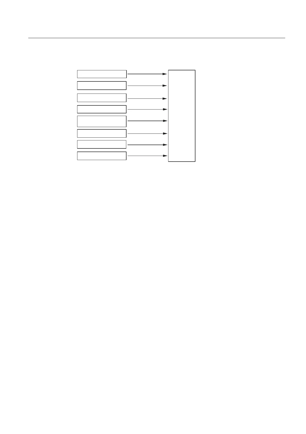
The figure below shows the parameters included in the calculation of the MTBF of a system.
&RPSRQHQW
FKDUDFWHULVWLFV
07%)RIWKH
V\VWHP
([SHULHQFH
(UURUPRGHO
0DUNRYPRGHO
0'7&&)'&
6\VWHPHUURU
0&6FODVV
0LQLPDO&XW6HW0&6
Figure A-2 MTBF
Requirements
This analysis assumes the following conditions:
● The failure rate of all components and all calculations is based on an average
temperature of 40 °C.
● The system installation and configuration is free of errors.
● All replacement parts are available locally, in order to prevent extended repair times due
to missing spare parts. This keeps the component MDT down to a minimum.
● The MDT of individual components is 4 h. The system's MDT is calculated based on the
MDT of the individual components plus the system structure.
● The MTBF of the components meets the following standards:
– SN 29500
This standard is compliant with MIL–HDBK 217–F.
– IEC 60050
– IEC 61709
● The calculations are made using the diagnostic coverage of each component.
● A CCF factor between 0.2% and 2% is assumed, depending on the system configuration.

 Loading...


