Procedural functions of press brakes
© Siemens AG 2003 All Rights Reserved
SIMOTION Safety Unit (AP) - Edition 06.2003
7-57
7.5.4 Valve control
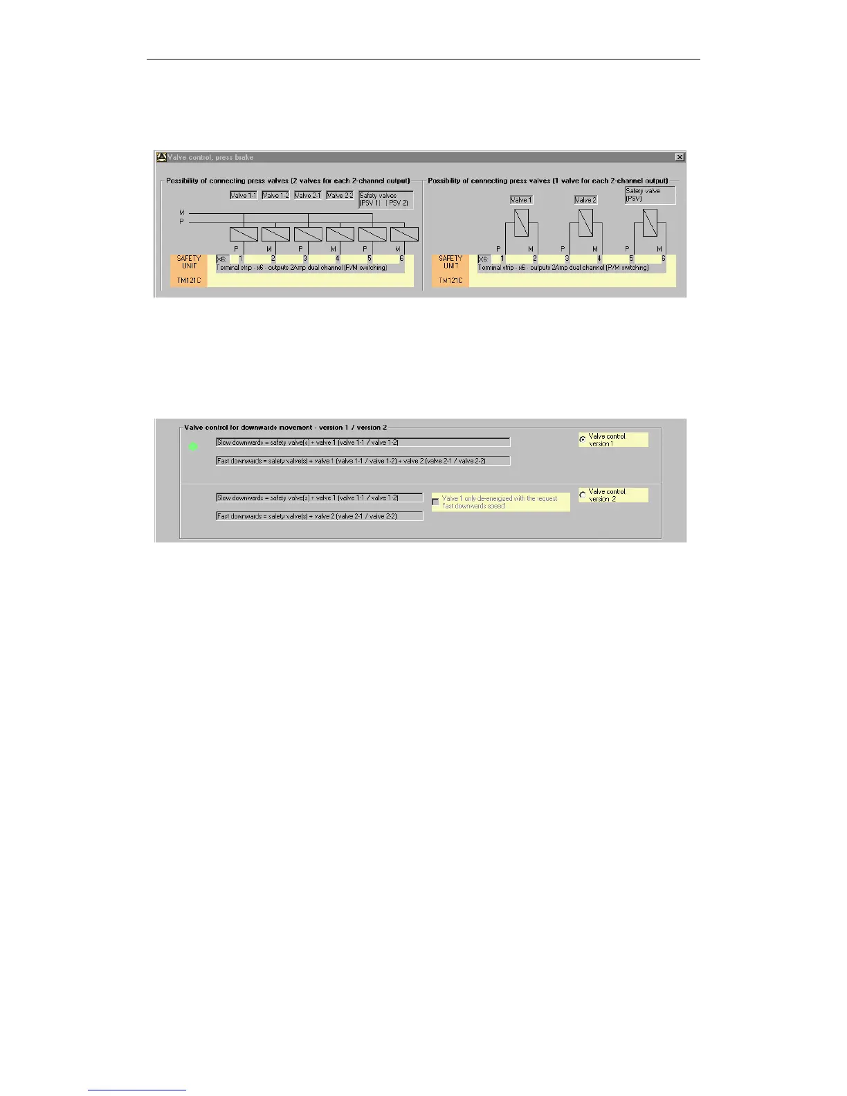
Figure 7-5 Valve control, part 1
The valve control can be implemented in accordance with performance
requirements.
A maximum of 3 valve pairs can be controlled. For the switching variant on the left,
the maximum possible output current is doubled (with equal loading of both the P
and M switches).
Figure 7-6 Valve control, part 2
One of two valve control variants can be selected:
• Variant 1
Here the press safety valve and valve 1 (or valve pair 1) are controlled for the
slow downward movement. All 3 valves (or valve pairs) are controlled for the
fast downward movement.
• Variant 2
Here the press safety valve and valve 1 (or valve pair 1) are controlled for the
slow downward movement. The press safety valve and valve 2 (or valve pair 2)
are controlled for the fast downward movement.
For this variant, it can optionally be specified whether valve 1 (slow movement)
is to remain controlled after activation. The control is reset as soon as a safety
device "responds", the "fast" request is set, the upward movement is initiated
or the operating mode is changed.