2.3.3 X500 and X501 DRIVE-CLiQ interface
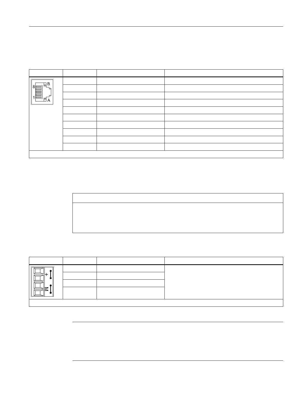
Table 2-2 DRIVE-CLiQ interface X500 and X501
Pin Signal name Technical specifications
1 TXP Transmit data +
2 TXN Transmit data -
3 RXP Receive data +
4 Reserved, do not use
5 Reserved, do not use
6 RXN Receive data -
7 Reserved, do not use
8 Reserved, do not use
A + (24 V) Power supply
B GND (0 V) Electronic ground
Blanking plate for DRIVE-CLiQ interface: Yamaichi, Article No.: Y-ConAS-13
2.3.4 X524 Electronic power supply
NOTICE
The Terminal Modules are reset upon interruption of the supply voltage.
It is essential to ensure that the external 24 VDC power supply to the terminal module is not
interrupted for longer than 3 ms. After an interruption of 3 ms, the command to reset the
component is issued, causing all outputs to be reset.
Table 2-3 Terminals for the electronic power supply
Terminal Designation Technical specifications
+ Electronic power supply Voltage: 24 V DC (20.4 V – 28.8 V)
Current consumption: max. 0.15 A
Max. current via jumper in connector:
20 A at 60 °C (15 A according to UL/CSA)
+ Electronic power supply
M Electronic ground
M Electronic ground
Max. connectable cross-section: 2.5 mm²
Note
The two "+" and "M" terminals are jumpered in the connector. This ensures that the supply
voltage is looped through.
The current consumption increases by the value for the DRIVE-CLiQ node. The digital outputs
are supplied via terminals X520, X521, and X522.
Terminal Module TM15
2.3 Description of Ports
TM15 / TM17 High Feature Terminal Modules
Manual, 11/2016 23