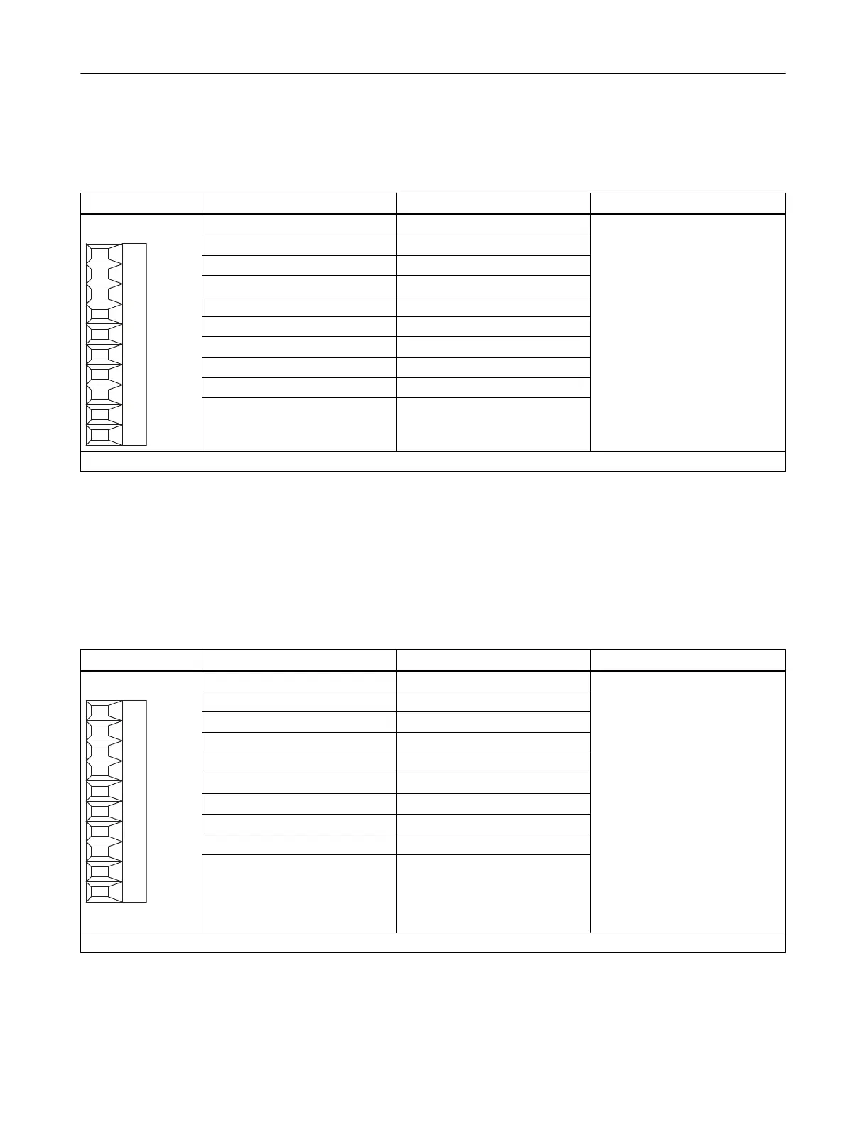
2.3.5 X520 digital inputs/outputs
Table 2-5 Screw terminal X520
Terminal Designation
1
Technical specifications
1 L1+ See chapter
"Technical specifications"
2 DI/O 0
3 DI/O 1
4 DI/O 2
5 DI/O 3
6 DI/O 4
7 DI/O 5
8 DI/O 6
9 DI/O 7
10 M1 (GND)
Max. connectable cross-section: 1.5 mm
2
1)
L1+: A 24 V DC power supply for DI/O 0 to 7 (first potential group) must always be connected if at least one DI/O of the potential group is used as output.
M1: A reference ground for DI/O 0 to 7 (first potential group) must always be connected if at least one DI/O of the potential group is used as either input or output.
DI/O: Digital input/output
2.3.6 X521 digital inputs/outputs
Table 2-6 Screw terminal X521
Terminal Designation
1
Technical specifications
1 L2+ See chapter
"Technical specifications"
2 DI/O 8
3 DI/O 9
4 DI/O 10
5 DI/O 11
6 DI/O 12
7 DI/O 13
8 DI/O 14
9 DI/O 15
10 M2 (GND)
Max. connectable cross-section: 1.5 mm
2
1
L2+: A 24 VDC infeed for DI/O 8 to 15 (second potential group) must always be connected when at least one DI/O of the potential group is used as an output.
M2: A reference ground for DI/O 8 to 15 (second potential group) must always be connected if at least one DI/O of the potential group is used as either input
Terminal Module TM15
2.3 Description of Ports
TM15 / TM17 High Feature Terminal Modules
Manual, 11/2016 25