or output.
DI/O: Digital input/output
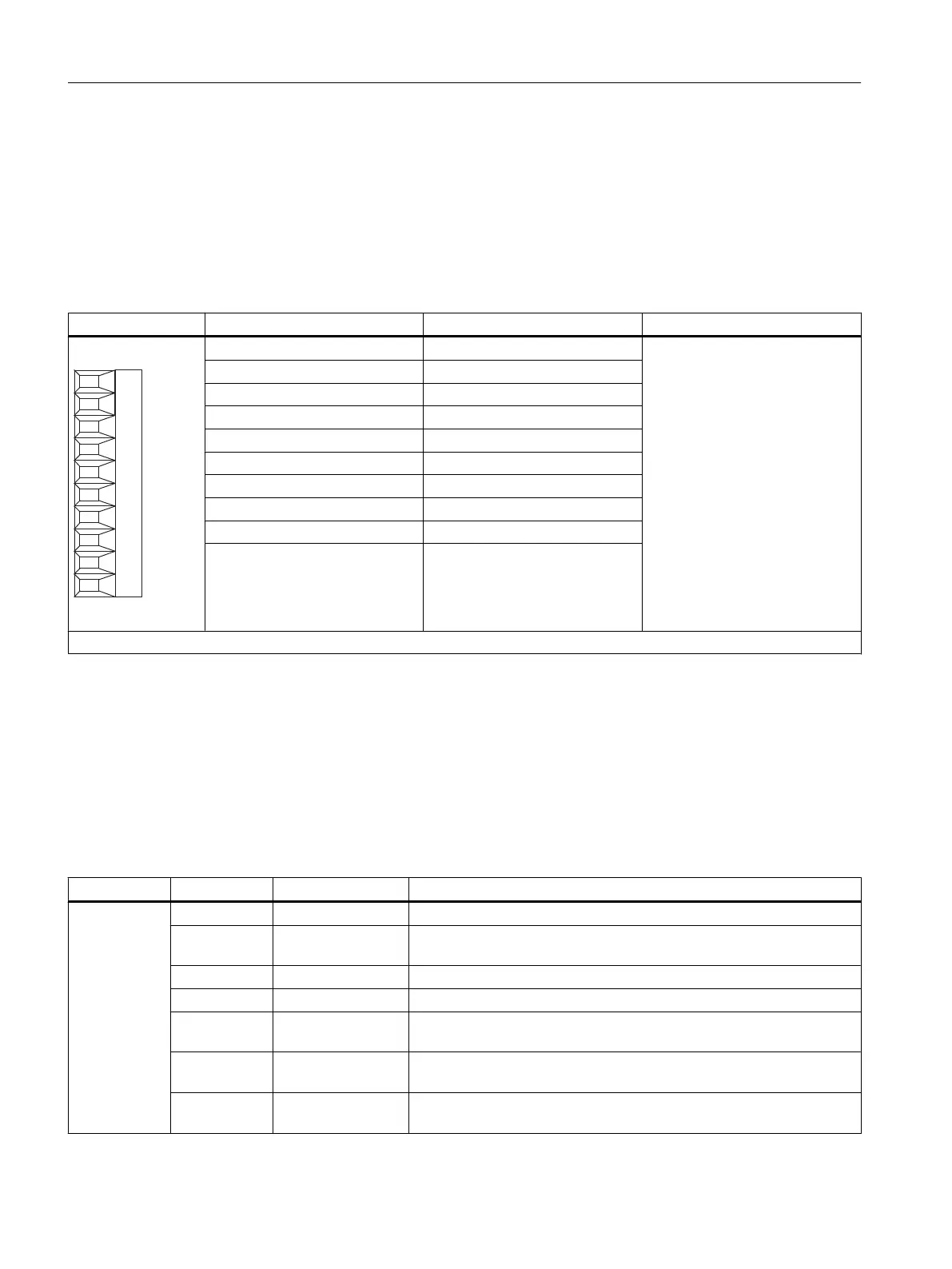
2.3.7 X522 digital inputs/outputs
Table 2-7 Screw terminal X522
Terminal Designation
1
Technical specifications
1 L3+ See chapter
"Technical specifications"
2 DI/O 16
3 DI/O 17
4 DI/O 18
5 DI/O 19
6 DI/O 20
7 DI/O 21
8 DI/O 22
9 DI/O 23
10 M3 (GND)
Max. connectable cross-section: 1.5 mm
2
1
L3+: A 24 V DC power supply for DI/O 16 to 23 (third potential group) must always be connected if at least one DI/O of the potential group is used as output.
M3: A reference ground for DI/O 16 to 23 (third potential group) must always be connected if at least one DI/O of the potential group is used as either input
or output.
DI/O: Digital input/output
2.3.8 Description of the LEDs on the Terminal Module TM15
Table 2-8 Description of the LED
LED Color State Description
READY
- OFF Electronics power supply outside permissible tolerance range.
Green Continuous The component is ready for operation and cyclic DRIVE-CLiQ com‐
munication is taking place.
Orange Continuous DRIVE-CLiQ communication is being established.
Red Continuous At least one fault is present in this component.
Green/red Flashing
2 Hz
Firmware is being downloaded.
Green/Or‐
ange
Flashing
2 Hz
Component detected: no fault present
Red/Orange Flashing
2 Hz
Component detected: Fault(s) present
Terminal Module TM15
2.3 Description of Ports
TM15 / TM17 High Feature Terminal Modules
26 Manual, 11/2016