2.6 Electrical Connection
It is always advisable to shield the digital input/output wiring.
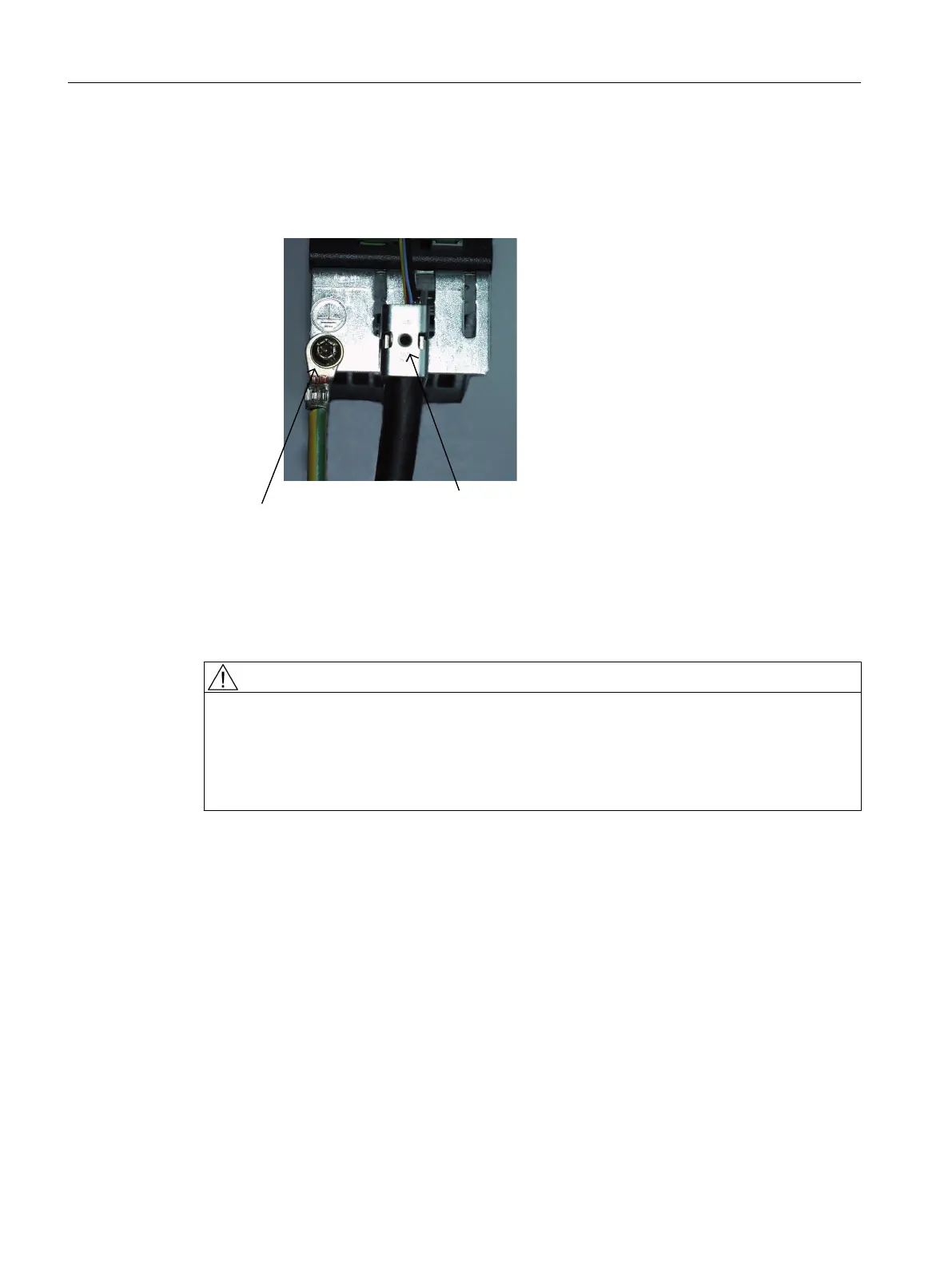
The following pictures show two typical shield connections from Weidmüller.
Weidmüller
Article No. KLBÜ CO 1
PE terminal
M4 / 1.8 Nm
Figure 2-5 Shield connections
Internet address of the company:
Weidmüller: http://www.weidmueller.com
WARNING
Danger to life through electric shock due to unconnected cable shields
Hazardous touch voltages can occur through capacitive cross-coupling due to unconnected
cable shields.
● As a minimum, connect cable shields and the cores of power cables that are not used
(e.g. brake cores) at one end at the grounded housing potential.
The TM15 housing is connected to the ground terminal of the module supply (terminal X524).
As long as the chassis is grounded, the housing is also grounded. An additional ground
connection using the M4 screw is especially necessary if high potential bonding currents can
flow (e.g. through the cable shield).
Terminal Module TM15
2.6 Electrical Connection
TM15 / TM17 High Feature Terminal Modules
30 Manual, 11/2016