3.3.5 X520 digital inputs/outputs
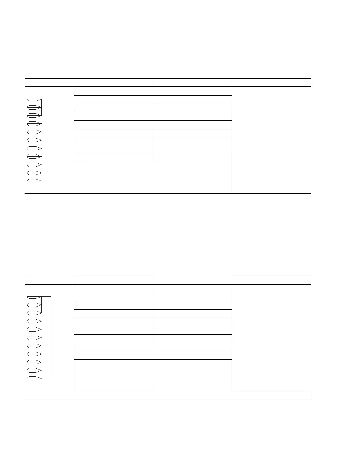
Table 3-5 Screw terminal X520
Terminal Designation
1
Technical specifications
1 M (GND) See chapter
"Technical specifications"
2 DI/O 0
3 DI/O 1
4 M (GND)
5 DI/O 2
6 DI/O 3
7 M (GND)
8 DI/O 4
9 DI/O 5
10 M (GND)
Max. connectable cross-section: 1.5 mm
2
1
M: Electronic ground for DI/O 0 to 15; if L1+ or L2+ is fed from a power supply other than the power supply connected via X524, the chassis ground of this
power supply (L1+ or L2+) must be connected to one of the M-terminals.
DI/O: Digital input/output
3.3.6 X521 digital inputs/outputs
Table 3-6 Screw terminal X521
Terminal Designation
1
Technical specifications
1 M (GND) See chapter
"Technical specifications"
2 DI/O 6
3 DI/O 7
4 M (GND)
5 L1+
6 L2+
7 M (GND)
8 DI/O 8
9 DI/O 9
10 M (GND)
Max. connectable cross-section: 1.5 mm
2
Terminal Module TM17 High Feature
3.3 Description of Ports
TM15 / TM17 High Feature Terminal Modules
42 Manual, 11/2016