Procedure:
1. Wire the free cable end of the connecting cable to the terminals on the drive unit. (The
terminal markings on the cable ends indicate the corresponding terminals for SIMODRIVE
devices.)
2. Open the front cover of the C230-2/C240 and connect the Sub-D socket (50-pin) to the X2
connector.
3. Lock the connector using the finger screws. Close the front cover.
Connecting cable
The connecting cable is a pre-assembled cable for four axes with an analog interface and
terminal designation for SIMODRIVE drive units.
The connecting cable is available in a choice of lengths.
See
Catalog PM 21, NC 60, or ST 70
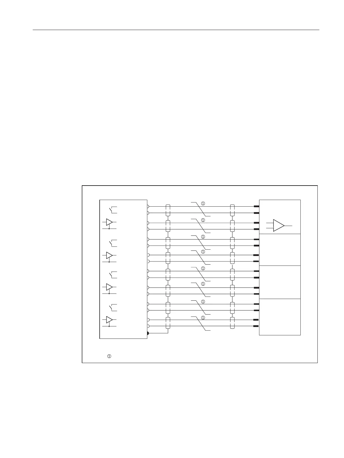
Wiring diagram
6KLHOGRQKRXVLQJ
:LUHVWZLVWHGDQGVKLHOGHGLQSDLUV
)HUUXOHVZLWKODEHO
6KLHOG
$[LV
$[LV
$[LV
,QSXWHQDEOH
9
6,027,21&
6,02'5,9(XQLYHUVDO
5()327
6(73
&75(1
&75(1
5()327
6(73
&75(1
&75(1
5()327
6(73
&75(1
&75(1
5()327
6(73
&75(1
&75(1
Figure 6-9 Terminal diagram for C230-2/C240 and SIMODRIVE 611 universal with analog setpoint
interface
Setpoint assignment
Connecting
6.1 Wiring
SIMOTION C
Operating Instructions, 11/2016, A5E33441428B 103