The assignment of the setpoints for axes 1 to 4 is fixed.
Setpoint output signals (X2) for drives with analog interface:
● SW1, BS1, RF1.1, RF1.2 for axis 1
● SW2, BS2, RF2.1, RF2.2 for axis 2
● SW3, BS3, RF3.1, RF3.2 for axis 3
● SW4, BS4, RF4.1, RF4.2 for axis 4
Note
When using the drive interface for standard outputs (C240 only), proceed as described in
chapter Onboard drive interface (C230-2, C240) (Page 48). Wire the free ends of the
connecting cable according to your application.
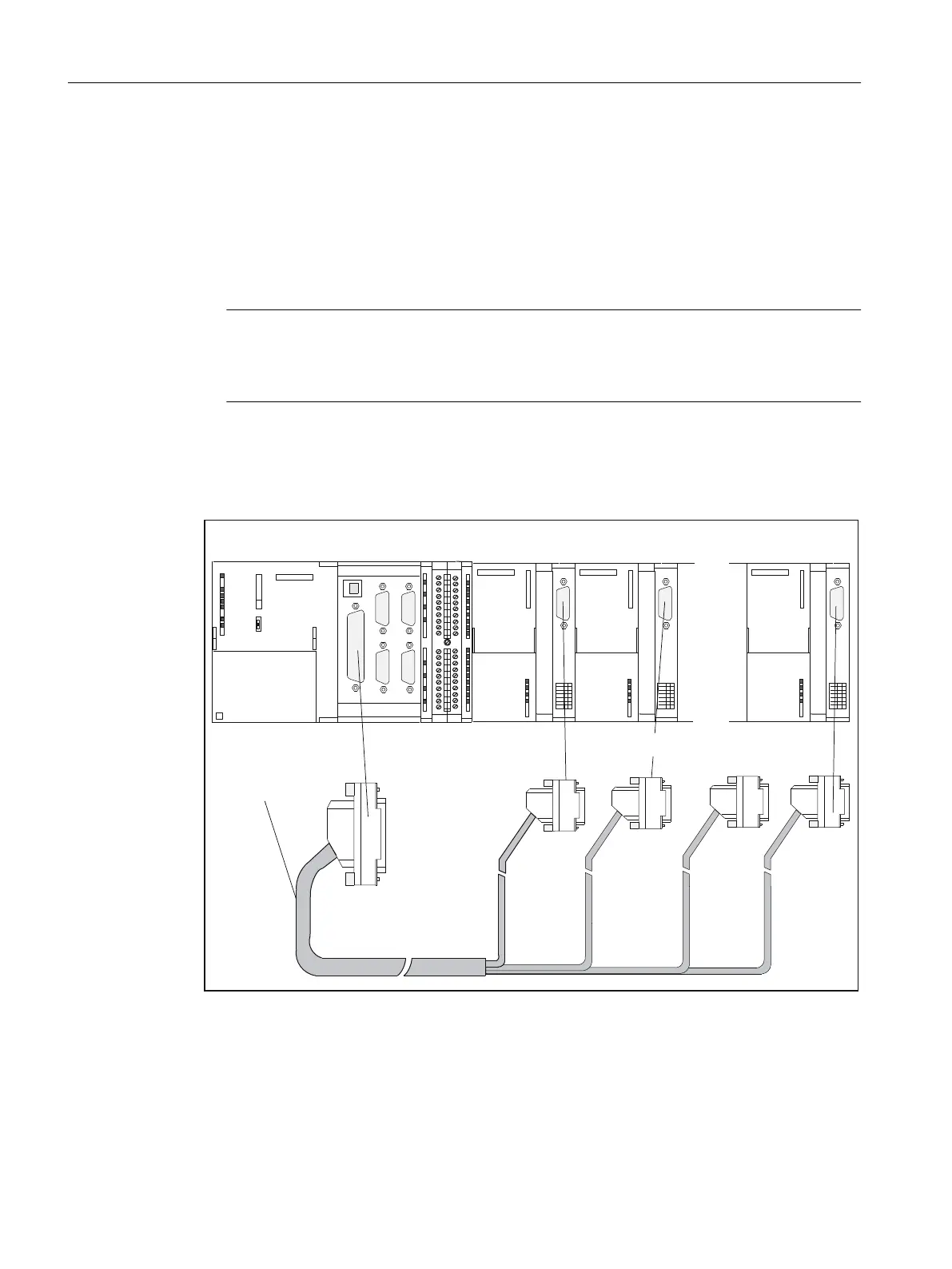
Connection of stepper drives (e.g. FM STEPDRIVE) to the onboard drive interface (C230‑2, C240)
The figure below shows the connection of the C230-2, C240 to FM STEPDRIVE drive units.
$[LV$[LV
$[LV
&RQQHFWLQJFDEOH
$[LV
&&
6,(0(166,(0(16
)067(3'5,9(
6,(0(16
;
;;
;;
;
6,(0(16
;
&
05(6
6723
581
Figure 6-10 Connection of FM STEPDRIVE drive units
Connecting
6.1 Wiring
SIMOTION C
104 Operating Instructions, 11/2016, A5E33441428B