● PULSE3, PULSE3_N, DIR3, DIR3_N, ENABLE3, ENABLE3_N for axis 3
● PULSE4, PULSE4_N, DIR4, DIR4_N, ENABLE4, ENABLE4_N for axis 4
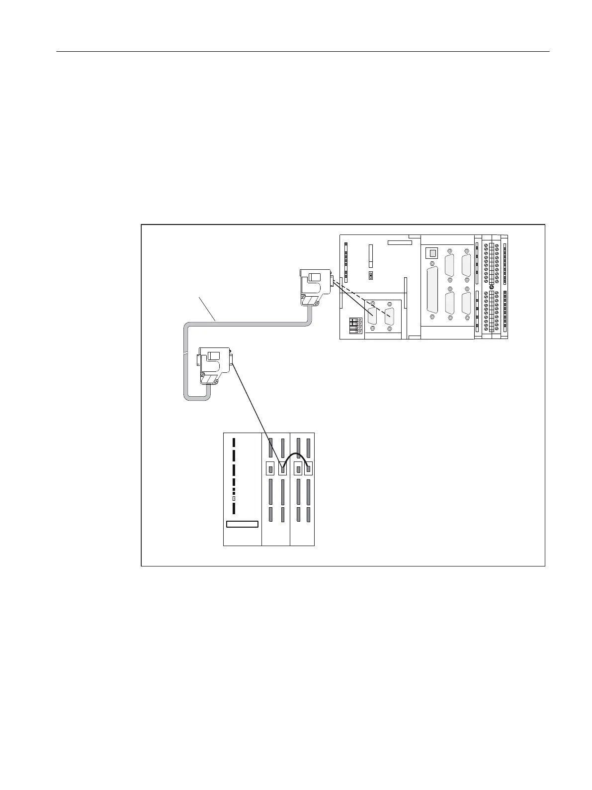
Connection of drives (e.g. SIMODRIVE 611 universal) to the PROFIBUS DP
The figure below shows the connection of the SIMOTION C to a SIMODRIVE 611 universal
drive unit.
Note that the "Motion Control with PROFIBUS DP" module must be fitted on the control unit
of your drive unit.
&RQQHFWLQJFDEOH
6,02'5,9(XQLYHUVDOGULYHXQLW
IRUH[DPSOH&
96$96$
6,02'5,9(
(5
6,(0(16
;
;;
;
;
;
6,(0(16
;
;
;
05(6
6723
581
&
Figure 6-12 Connection of SIMODRIVE 611 universal drive unit to PROFIBUS DP
Procedure:
1. Insert the Sub-D connector (9-pin) into the drive unit.
2. Open the front door of the SIMOTION C and insert the Sub-D connector (9-pin) into the X8/
X9 socket.
3. Lock the connector using the finger screws. Close the front cover.
Connecting
6.1 Wiring
SIMOTION C
Operating Instructions, 11/2016, A5E33441428B 107