Fitting the shield connecting element
Fit the shield connecting element as follows:
1. Push the two threaded studs for the retaining bracket into the guide on the underside of
the rail. Position the retaining bracket under the modules to be wired.
2. Screw the retaining bracket tight on the mounting rail.
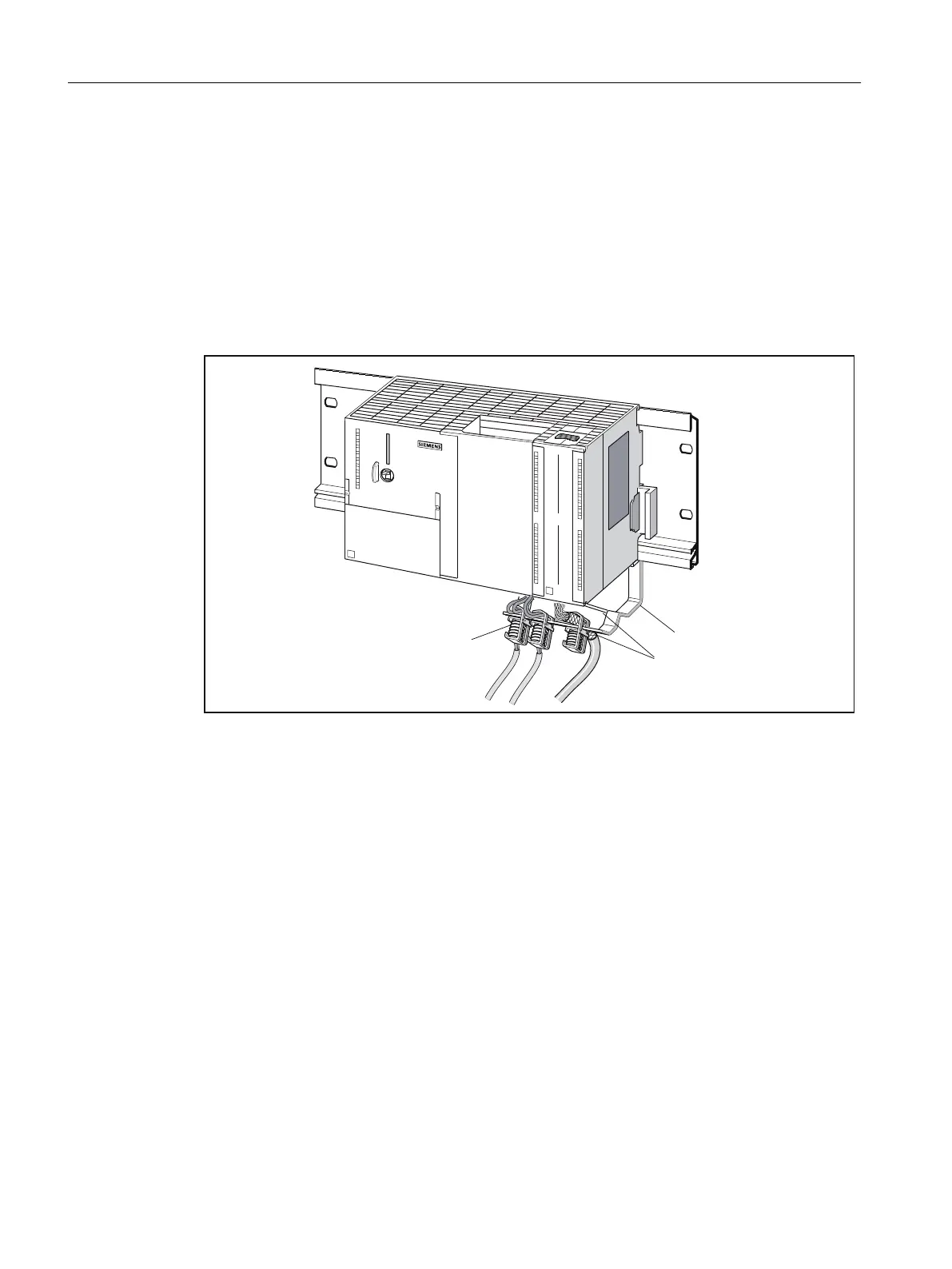
3. The bottom of the shield connection terminal consists of a web interrupted by a slot. Place
this part of the shielding terminal on edge a of the retaining bracket (see the following figure).
Press the shielding terminals down and pivot them into the required position.
You can fit a maximum of four shield terminals on each of the two rows.
)L[LQJEUDFNHW
6KLHOGWHUPLQDO
(GJHD
Figure 6-18 Fitting the shield connecting element
Laying the cables
Only one or two shielded cables can be attached per shielding terminal (see table "Assignment
of cable cross-sections and shielding terminals"). Attach the cable to the stripped cable shield.
The stripped section of cable shield must have a minimum length of 20 mm. If you require
more than four shielding terminals, start the wiring on the back row of the shield connecting
element.
Tip: Make sure you allow a sufficient length of cable between the shielding terminal and the
front connector. This will, for example, ensure that if a repair is required, you can unplug the
front connector without also having to remove the shield terminal.
Connecting
6.1 Wiring
SIMOTION C
118 Operating Instructions, 11/2016, A5E33441428B