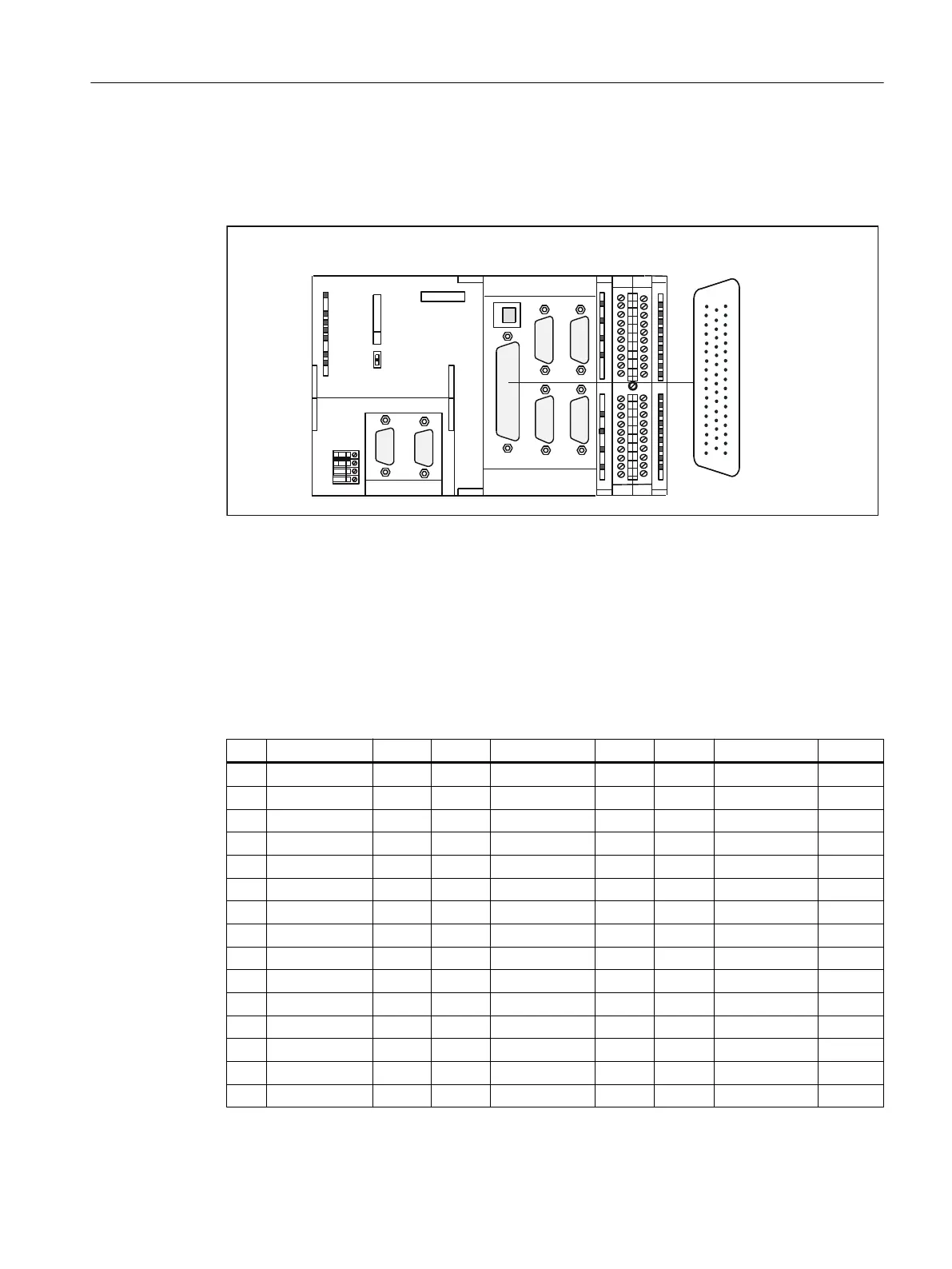
Position of the connector
The following figure shows the installation position and the designation of the connector on
the module.
;
;
;;
;;
;
;'303,;'3
&
6,(0(16
;
05(6
6723
581
$1$/2*287
67(33(5&75/
Figure 4-5 Position of the X2 connector
Connector pin assignment
Onboard drive interface (servo interface, 4 axes)
Connector designation: X2 ANALOG OUT 1-4/STEPPER CTRL 1-4
Connector type: 50-pin Sub-D plug connector
Table 4-6 X2 connector pin assignment
Pin Name Type Pin Name Type Pin Name Type
1 SETP1 VO 18 ENABLE1 O 34 REFPOT1 VO
2 REFPOT2 VO 19 ENABLE1_N O 35 SETP2 VO
3 SETP3 VO 20 ENABLE2 O 36 REFPOT3 VO
4 REFPOT4 VO 21 ENABLE2_N O 37 SETP4 VO
5 PULSE1 O 22 GND O 38 PULSE1_N O
6 DIR1 O 23 GND O 39 DIR1_N O
7 PULSE2_N O 24 GND O 40 PULSE2 O
8 DIR2_N O 25 GND O 41 DIR2 O
9 PULSE3 O 26 ENABLE3 O 42 PULSE3_N O
10 DIR3 O 27 ENABLE3_N O 43 DIR3_N O
11 PULSE4_N O 28 ENABLE4 O 44 PULSE4 O
12 DIR4_N O 29 ENABLE4_N O 45 DIR4 O
13 Not assigned 30 Not assigned 46 Not assigned
14 CTREN1.1 C 31 Not assigned 47 CTREN1.2 C
15 CTREN2.1 C 32 Not assigned 48 CTREN2.2 C
Interfaces
4.5 Onboard drive interface (C230-2, C240)
SIMOTION C
Operating Instructions, 11/2016, A5E33441428B 49