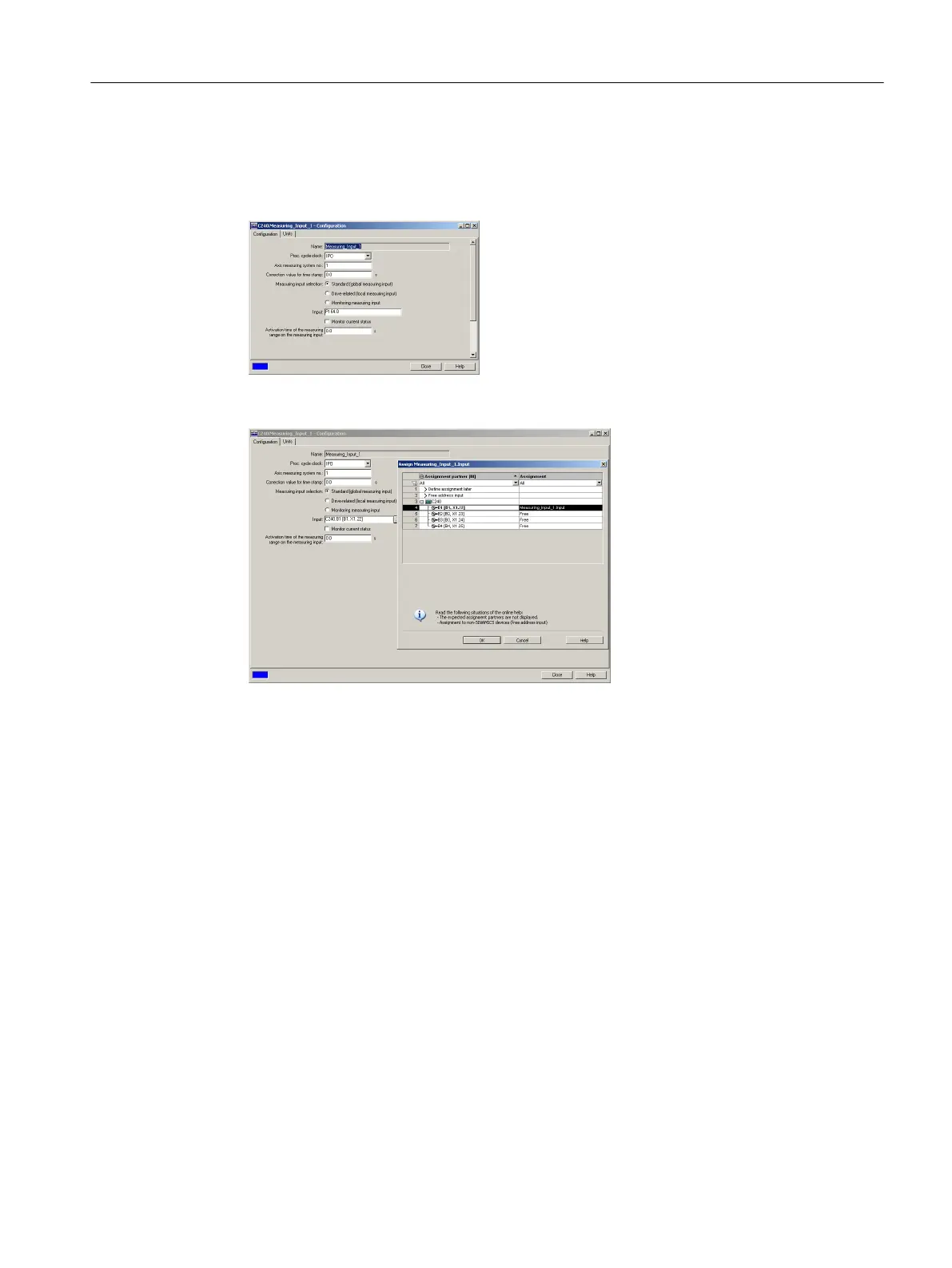
The measuring input must be configured as follows:
1. Activate global measuring.
2. Assign to the input e.g. PI 64.0 or use symbolic assignment (e.g. C240.B1 [B1, X1.22]).
Figure 4-15 Configuration example for global measuring (without symbolic assignment)
Figure 4-16 Configuration example for global measuring (symbolic assignment)
With a signal edge at the measurement input, the current actual value of the assigned encoder
is recorded with an exact position.
Digital outputs (onboard)
Eight digital outputs (Q0 to Q7) are provided on the SIMOTION C. These can also be
interconnected via symbolic assignment using variables as of SIMOTION V4.2 for C240 and
C240 PN.
These fast outputs (onboard) can be used as freely addressable process outputs or as "fast
output cams" (position switching signals). Addresses are allocated in the hardware
configuration. The outputs are subject to a signal delay, see Technical data (Page 163).
For repeat accuracy when using the outputs as fast output cams, see Versions of SIMOTION
C (Page 33).
READY output
The ready signal (RDY.1, RDY.2) is an isolated contact assembly (make contact).
The contact can be used for the safe shutdown of parts of the system, for example, through
integration in the EMERGENCY STOP circuit.
Interfaces
4.8 I/O interface
SIMOTION C
Operating Instructions, 11/2016, A5E33441428B 75