Pin assignment
The table below shows the pin connections on the screw-type terminal block.
Table 6-6 Assignment of the screw-type terminal block
Terminal Pin assignment
Functional ground
M Ground
L+ 24 V DC
M Ground
If you want to ground the reference potential, you must not remove the jumper between
terminals M and functional ground on the SIMOTION C.
Line buffering
The PS 307 load current supplies from the S7-300 system guarantee mains buffering for 20
ms.
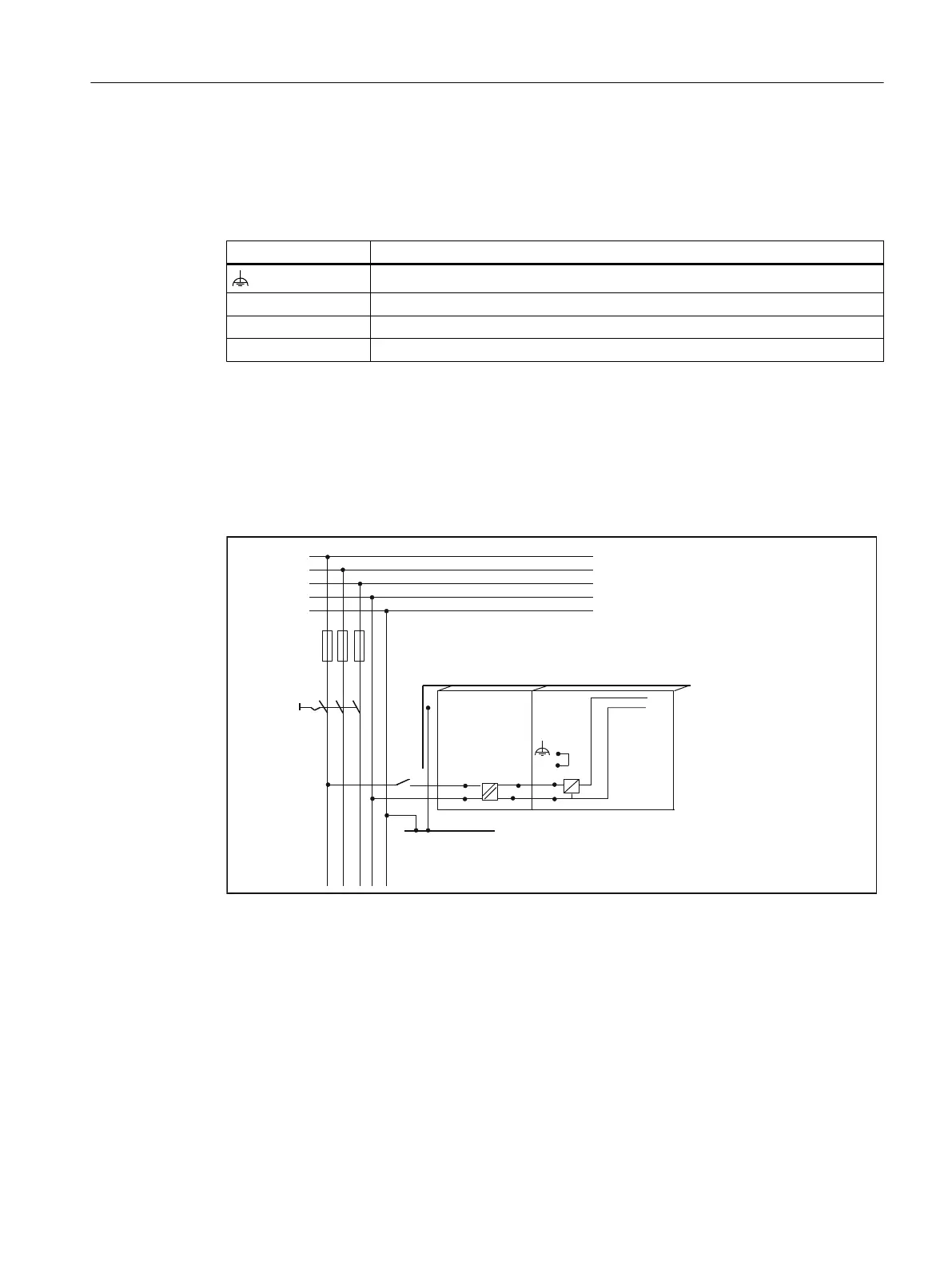
/RZYROWDJHGLVWULEXWLRQ
HJ716V\VWHP[9
*URXQGLQJEDU
LQFDELQHW
0RXQWLQJUDLO
/
/
/
1
3(
1
6,027,21&
36
0
0
/
/
0
Figure 6-6 Module supply options
Supply system lines
Use flexible cables with a cross-section of 0.25 to 2.5 mm
2
(or AWG 18 to AWG 14) for wiring
the power supply.
If you only use one wire per connection, a ferrule is not required.
You can use ferrules without an insulating collar in accordance with DIN 46228, Form A long
version.
Connecting
6.1 Wiring
SIMOTION C
Operating Instructions, 11/2016, A5E33441428B 99