SIMOVERT P 6SE21 Series Inverters
English
Operating Instructions
Siemens plc 1995
G85139–A1615–U156–A
02.95
15
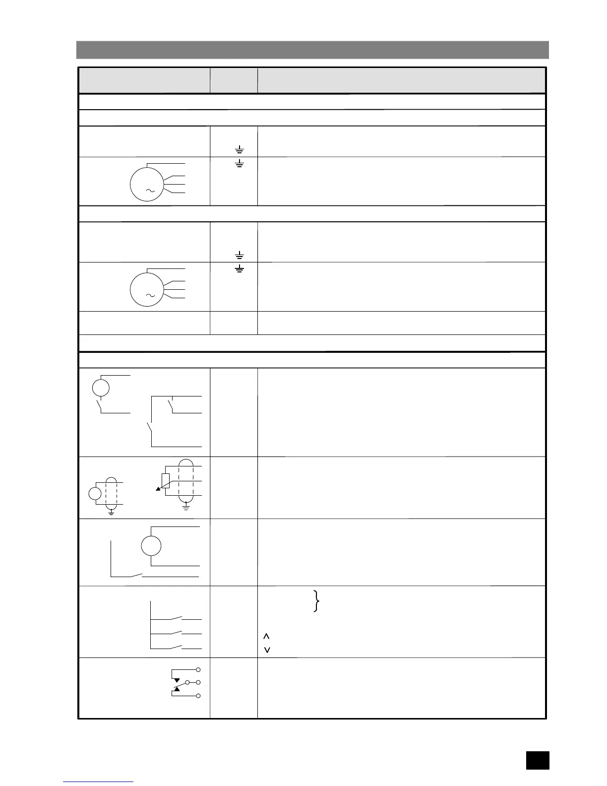
POWER TERMINALS: TERMINAL BLOCK X1
Single Phase Input Units:
Connection
Terminal
Labelling Function, Data, Notes
U1 X1.L1
Mains
N1 X1.N
PE X1. Ground
PE X1. Ground
U2
V2
W2
X1.U
X1.V
X1.W
Motor connection 3AC 0 V ... Line voltage
0.0 ... 400 Hz
M
3
Three Phase Input Units:
U1 X1.L1
V1
W1
PE
X1.L2
X1.L3
X1. Ground
Mains connection 3AC 380 – 500 V +/–10%
50/60 Hz
PE X1. Ground
U2
V2
W2
X1.U
X1.V
X1.W
Motor connection
0.0 ... 400 Hz
M
CONTROL TERMINALS: TERMINAL BLOCK X11
X11.1
X11.2
X11.3
X11.4
X11.5
X11.6
X11.7
X11.8
X11.9
X11.10
X11.11
X11.12
=
+
24 V
0 V 100 k connection to ground
Run/Stop Level or edge–triggered (P05)
+15 V
Forward/Reverse Closed = reverse
+10 V Ref. Reference voltage for potentiometer
0...10 V Frequency setpoint (voltage) (P04)
0 V
0 (4)...20 mA Frequency setpoint (current) (P04)
0 V
0...10 V Frequency/Output current indication
0...50 V Tachometer input
1AC 220 – 240 V +/–10% 50/60 Hz
5 k
=
+
–
Tacho
3
Figure 3:
Connection Diagram
X11.13
Jog Jog speed set by parameter P12
Ω
DC – Output X1.–
Connections for Braking Module (EBM)
DC + Output X1.+
Trip Can be used in conjunction with Run/Stop
and with PTC
X11.14
X11.15
X11.16
X11.17
A
RS485 Serial I/O connection
B
‘P’ Button connection
‘
’ Button connection
X11.18 ‘ ’ Button connection
X11.2
X11.19
X11.20
X11.21
X11.22
NO Fault indication
COM
NC
0 V
(energised during normal operation)
3AC 0 V ... Line voltage
X11.2
Use Class 1 60/75
o
C copper wire only. The tightening torque for field wiring terminals is 1.5 Nm (M4).
max. load 5 mA
(10 V f
max
/I
max
)
 Loading...


