SIMOVERT P 6SE21 Series Inverters
English
Operating Instructions
Siemens plc 1995
G85139–A1615–U156–A
02.95
10
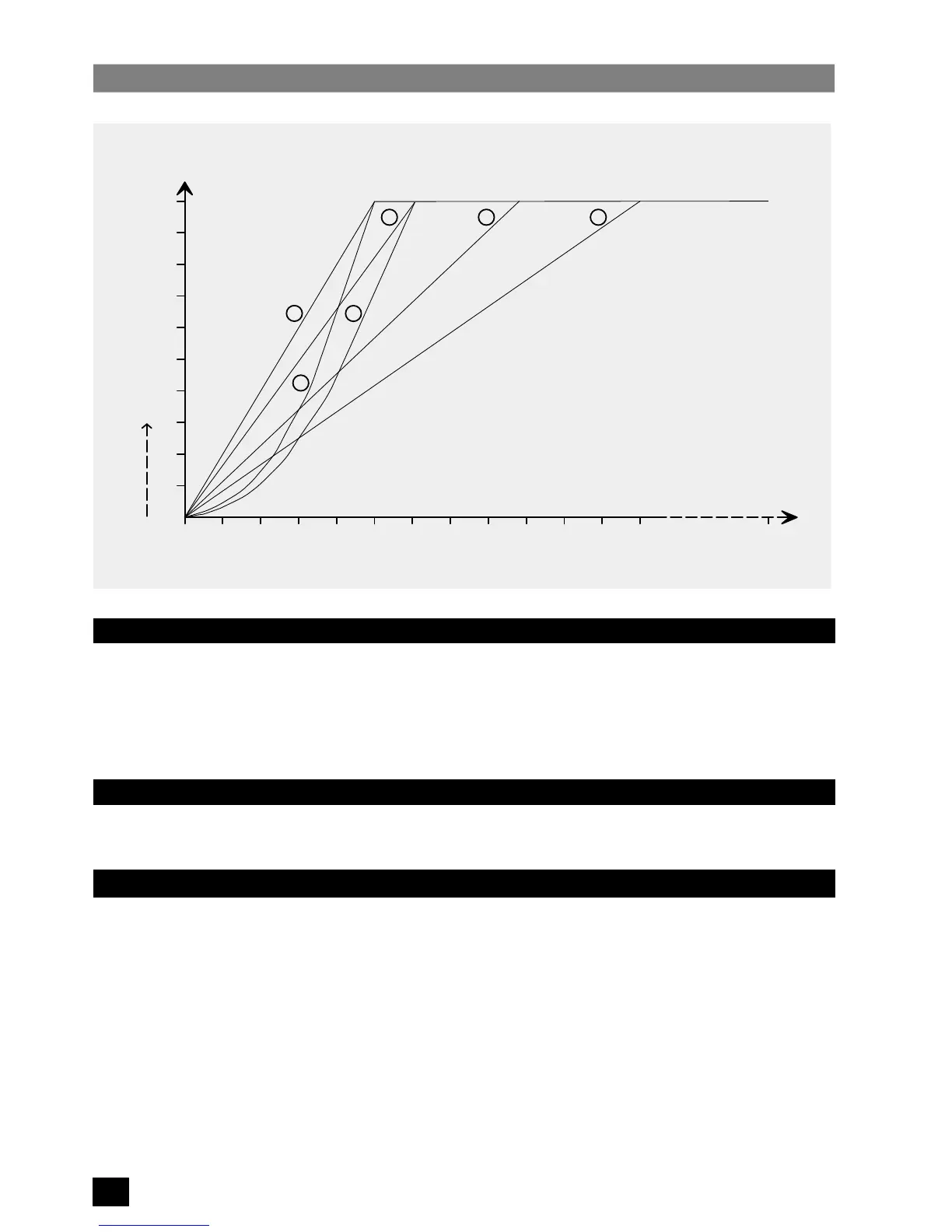
Figure 2:
Voltage/Frequency Characteristic Curves
0 10 20 30 40 50 60 70 80 90 100 110 120
10
20
30
40
50
60
70
80
90
100
Voltage
%
Frequency
0
1 2 3
4
5
Boost
Ku
400
1.4.2 Low Frequency Voltage Boost (Ku)
The output voltage can be boosted in 0.1% steps up to 30% for low frequencies from 0 Hz. This may be required to give
additional starting torque in some applications. The amount of voltage boost decreases linearly until 100% voltage is
achieved.
If required, automatic boost may be used
(see section 5.3.2, Parameter P19)
. This measures the motor characteristics
and selects a suitable boost voltage at first switch–on.
1.4.3 Current Limit
The maximum output current available from the inverter can be adjusted to provide thermal protection of the motor
and/or limit the maximum motor torque
(see section 5.3.2, parameters P17 and P18)
.
1.5 Options
The following options are available for use with 6SE21 inverters:
Sinewave Filter Module Part No. 6SE2100–1FC51/53/55
NAMUR Interface Module Part No. 6SE2100–1FC50/52/54
Relay Module * Part No. 6SE2100–1GA00
Tachometer Interface Unit * Part No. 6SE2100–1DA00
Clear Text Operator Panel * Part No. 6SE2100–1CA00
*
These options cannot be fitted in combination with each other.
 Loading...


