SIMOVERT P 6SE21 Series Inverters
English
Operating Instructions
Siemens plc 1995
G85139–A1615–U156–A
02.95
30
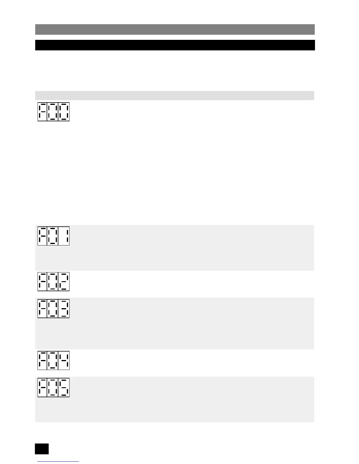
5.4 Fault Indications
In the event of a fault condition arising, the inverter will stop and the display will indicate F, followed by a two–digit code
(see
Figure 5
below)
.
Fault Code Cause Corrective Action
Excessive load current
or
Excessive link voltage
or
Low line voltage
(models 6SE21**–3AA21 only).
Ensure rating plate on motor corresponds with inverter rating
(see section 2.1)
.
A low frequency voltage boost may be required to start the motor
(refer to section
5.3.2, P01)
.
The characteristic voltage/frequency curve of the inverter may not match that
required by the motor
(refer to section 5.3.2, P06)
.
The acceleration time for the motor may be too short
(refer to section 5.3.2, P02)
.
Check whether the motor has stalled or is overloaded.
Check for short–circuits or ground faults on the output leads.
Ensure line voltage is within the limits specified on the inverter rating plate.
The deceleration time of the motor may be too short
(refer to section 5.3.2, P03)
.
Check that the voltage of all three input power phases is within the limits specified
on the inverter rating plate.
Excessive heatsink temperature. Check that the unit has been installed with at least 100 mm clear space above it
for exhaust air and that the air inlet at the bottom of the unit is not obstructed.
Check that the ambient temperature is below 40
o
C.
Check that the steady motor current is not above the limit specified on the rating
plate.
Corruption of parameterisation data
in the non–volatile memory.
Reset all parameters
(see section 5.3)
. Recalibrate the current monitor by
removing power from the inverter, pressing all three parameterisation buttons
simultaneously while applying power to the inverter. The display will indicate ‘CAL’
for several seconds while it recalibrates the monitor circuit.
Faulty operation of the
analogue–to–digital converter.
Excessive tachometer feedback
voltage.
Check that the analogue input voltage on terminal X11.7 is less than +12 V and
greater than –0.5 V.
If operating in current loop control, check that the current entering control terminal
X11.9 is less than 25 mA and greater than –1 mA.
Ensure tachometer output does not exceed 50 V at terminal X11.12.
The minimum frequency parameter
(P07) has been set to a higher
value than the maximum frequency
parameter (P08).
Reset parameter P07 or P08.
The fixed frequency parameter
(P09) has been set outside the
minimum/maximum frequency
limits set by parameters P07 &
P08. Note that this fault indicator
will only be enabled if P04 is set to
003.
Reset parameter P07, P08 or P09.
Figure 5:
Fault Code Table (Sheet 1 of 2)
 Loading...


