SIMOVERT P 6SE21 Series Inverters
English
Operating Instructions
Siemens plc 1995
G85139–A1615–U156–A
02.95
8
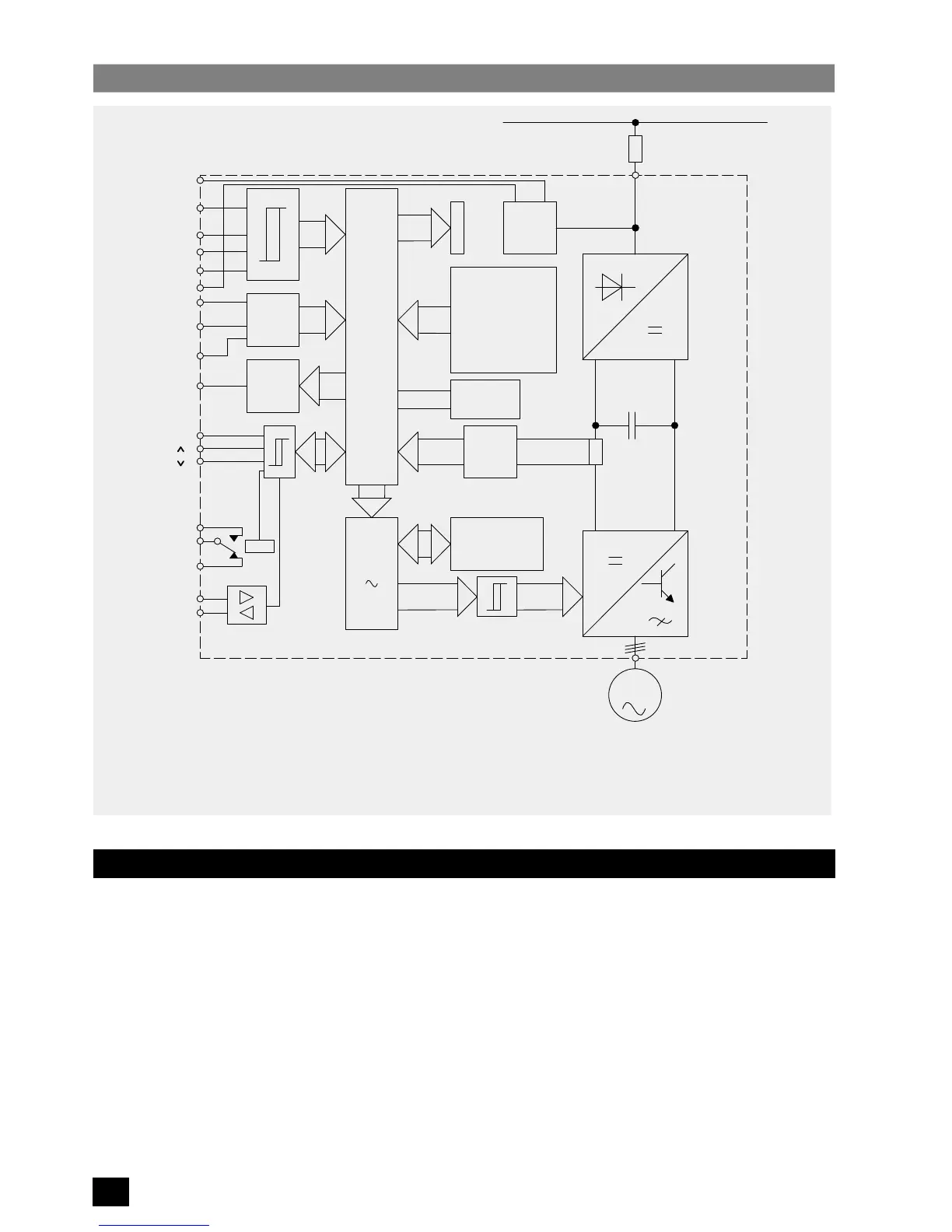
Block Diagram – SIMOVERT P 6SE21
Figure 1:
3
M
PWM
SE
PROM
CPU
A/D
D/A
SV
SI
GR
ZK
WR
Run/Stop
0 – 10 V
0 – 20 mA
4 – 20 mA
BUS
+
Power Supply
Mains Fuse(s)
DC Link
Power Supply
Microprocessor
Analog/Digital Converter
Bus Connector
GR Rectifier
WR Inverter
SE Current Monitoring
PWM Pulse Width Modulator
D/A Digital/Analog Converter
R/L Clockwise/Counter–clockwise
Frequency, Current Indicator
Jog
FRONT
PANEL
F
u
/I
u
PROM
Fault
Trip
Tacho
F
u
/I
u
P
RS485
X11
X1
X1
ZK
CPU
A/D
BUS
+15 V
+10 V
2
3
4
13
6
7
9
12
11
16
17
18
19
20
21
14
15
SI
SV
R/L
5
1.2 Control Facilities
The inverter can be started/stopped by any of the following means
(see parameter P05 in section 5.3.2 and also Figure
3)
:
(1) Connection of a latching switch to the run/stop input (terminals X11.2/3).
(2) Applying a rising edge (i.e. momentary push–button) to the Run/Stop input (terminals X11.2/3) and a falling
edge to the trip input terminal X11.2/4.
(3) Connection of a voltage level of 7 – 33 V to the Run/Stop input (terminals X11.3/1).
(4) Automatic starting on application of input power (shorting link terminals X11.2/3).
(5) Connection of a voltage level of 7 – 33 V to the jog input (terminal X11.13/1).
(6) Control via the serial I/O connections.
 Loading...


