SIMOVERT P 6SE21 Series Inverters
English
Operating Instructions
Siemens plc 1995
G85139–A1615–U156–A
02.95
34
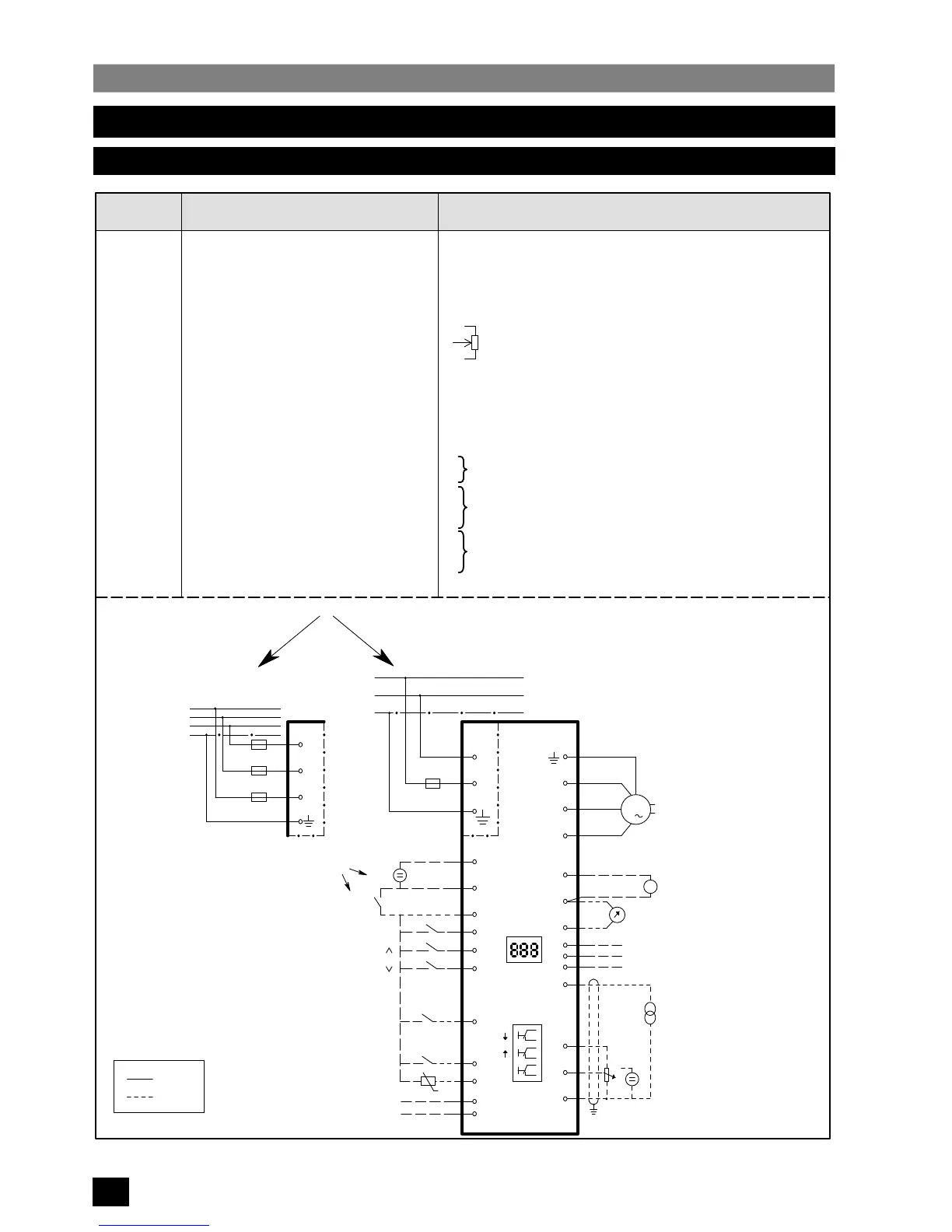
7. QUICK REFERENCE GUIDE
7.1 Connections
Function
0 V Connection
+15 V
Run Connection
Trip
Forward / Reverse
10 V
Frequency Adjust Voltage
0 V
Frequency Adjust Current
0 V
Frequency / Current Indication
Tachometer
Jog
A
B
P
∧
∨
Fault Indication NO
Fault Indication Common
Fault Indication NC
0 V
P
SIMOVERT P
N
L1
1
3
2
5
W
V
U
12
10
11
9
6
7
8
X1 X1
L1
N
PE
Mains
L3
L2
X1
L1
L1
L2
L3
PE
Mains
Motor
Tachometer
Frequency/Output Current Indicator
Essential
Optional
OR
X11
X11
0..10 V
0..20 mA
4..20 mA
Frequency setpoint
(analogue)
RUN
Forward/Reverse
+
+
13
Jog
20
21
19
Fault Indication to
External Alarm
17
18
16
P
14
15
Serial
Comms
RS485
4
Trip
PTC
+
RUN
OR
OR
0 V
R/S
+15 V
M
3
Terminal
1
2
3
4
5
6
7
8
9
10
11
12
13
14
15
16
17
18
19
20
21
22
Remarks
Apply voltage or connect to +15 V to run
Normally closed trip input when P05 = 4, etc.
Apply voltage or connect to +15 V to reverse
0 – 20 mA or 4 – 20 mA input
Output for frequency (F
max
) or current (I
max
) monitor
Analogue tachometer or sensor input
External jog button connection
RS485 serial connection
Push–button connections
Fault relay output
10k
Typical frequency
control arrangement
1AC 220 – 240 V, 50/60 Hz
3AC 380 – 500 V, 50/60 Hz
 Loading...


