SIMOVERT P 6SE21 Series Inverters
English
Operating Instructions
Siemens plc 1995
G85139–A1615–U156–A
02.95
31
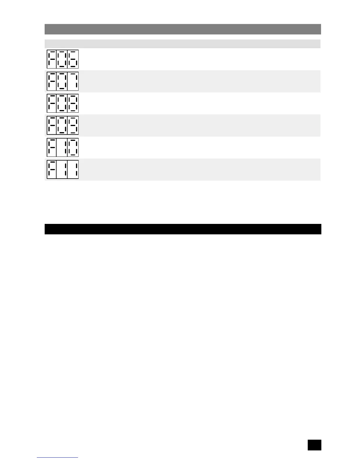
Fault Code Cause Corrective Action
Control board fault. Disconnect the inverter from the input power supply and then reconnect.
Parameter P25 set above
maximum frequency P08 or below
minimum frequency P07.
Change parameter P25, P08 or P07.
Parameter P26 set above
maximum frequency P08 or below
minimum frequency P07.
Change parameter P26, P08 or P07.
Parameter P27 set above
maximum frequency P08 or below
minimum frequency P07.
Change parameter P27, P08 or P07.
Parameter P28 set above
maximum frequency P08 or below
minimum frequency P07.
Change parameter P28, P08 or P07.
Inverter externally tripped via X11.4
input.
Clear external trip on X11.4 and restart the inverter.
Figure 5:
Fault Code Table (Sheet 2 of 2)
If a fault indication has been observed and the corrective action implemented, the inverter can be reset by applying a
STOP (low) signal to the run/stop input (terminal X11.3) followed by a RUN (high) signal to the same input.
Alternatively, the incoming mains voltage can be switched off and then switched on again.
5.5 Fault Relay
A single pole changeover relay is provided to indicate a fault. It is normally energised when the inverter is powered and
operating or stopped. If a fault condition occurs, the relay will be de–energised. The contacts of the relay are connected
to terminals X11.19 (normally open, de–energised), X11.20 (common) and X11.21 (normally closed, de–energised) on
the control board.
 Loading...


