Controlling the safety functions
5.2 Control of "STO" and "SS1" via terminal module for option K82
Safety Integrated
36 Function Manual, 07/2016, A5E03264275A
Forced checking procedure
The maximum value for the forced checking procedure interval when using option K82 is
6 months (4380 h).
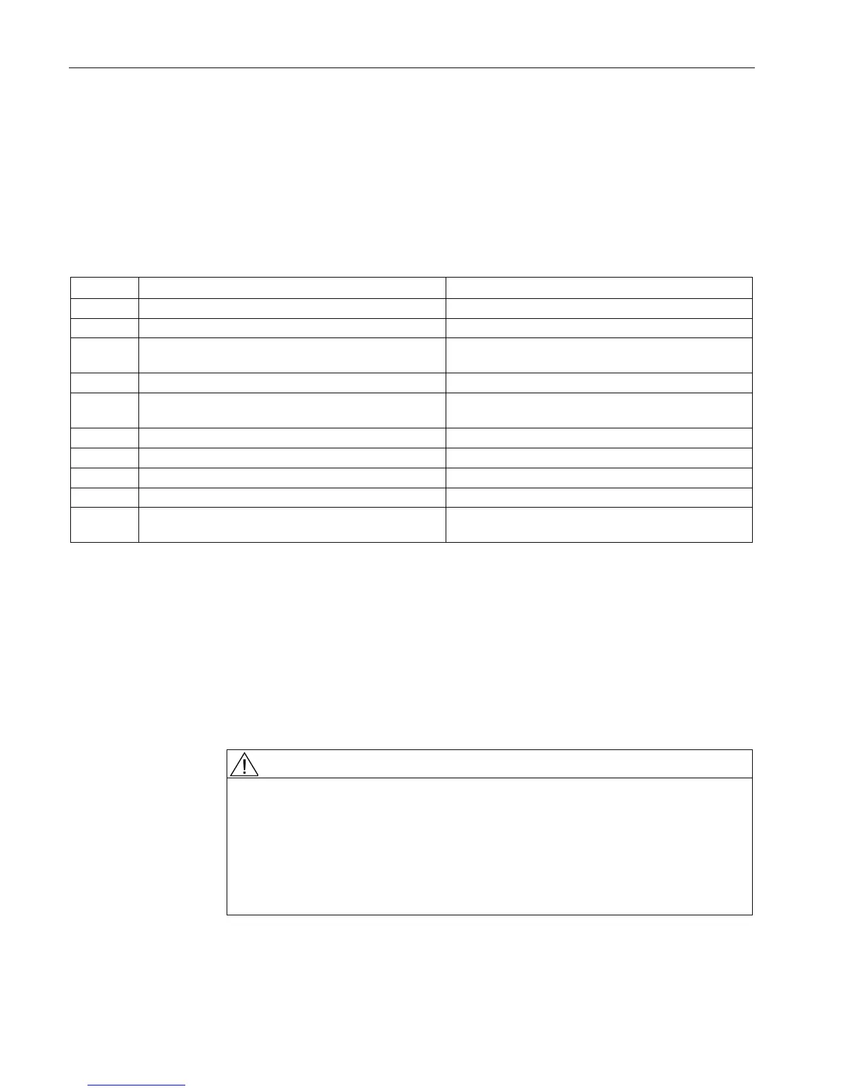
Table 5- 2 Terminal strip -X41
Connection for actuating element at channel 1 "+"
-X41:2 Connected to -X41:1
-X41:3 Control of -K41:A2, -K42:A2 , N conductor or ground Connection of reference potential for actuating ele-
ments at channel 1 and channel 2
-X41:4 Connected to -X41:3
-X41:5 Feedback signal, status -K41, -K42 Connection of supply voltage for optional feedback
Feedback signal, status -K41, -K42
Connection of optional checkback signal
Connection for actuating element at channel 2 "+"
-X41:10 Output -K41: Permanently wired with CU320-2:
Rated voltage: 24 VDC to 230 VAC (0.85 ... 1.1 x Us)
Max. line length (applies to the sum of the outgoing and return lines):
● AC (line capacity: 300 pF/m):
– 24 V: 5000 m
– 110 V: 800 m
– 230 V: 200 m
The values apply for 50 Hz, at 60 Hz the line lengths must be reduced by 20%.
Danger to life as a result of exceeding the permissible cable lengths and/or the
permissible cable capacitances
When the permissible cable lengths and/or the permissible cable capacitances are
exceeded, the relay can remain energized as a result of the coupling capacitances of
the cable and the associated residual current, in spite of the fact that the actuating
elements are open. Death and serious injury can result in the event of an error.
• Do not exceed the maximum permissible cable lengths and cable capacitances.
● DC (min. cross-section 0.75 mm²): 1500 m

 Loading...


