Controlling the safety functions
5.3 Control of "STO" and "SS1" via terminals on the Control Unit and the Motor/Power Module
Safety Integrated
Function Manual, 07/2016, A5E03264275A
55
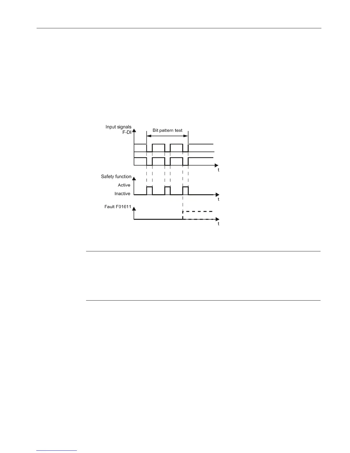
Bit pattern test
Bit pattern test of fail-safe outputs
The converter normally responds immediately to signal changes in its fail-safe inputs. This is
not desired in the following case: Several control modules test their fail-safe outputs using bit
pattern tests (light/darkness tests) to identify faults due to either short-circuiting or cross
circuiting. When you interconnect a fail-safe input of the converter with a fail-safe output of a
control module, the converter responds to these test signals.
Figure 5-6 Converter response to a bit pattern test
Note
Debounce time for unwanted triggering of Safety Integrated functions
If the test pulses cause an unwanted triggering of the
Safety Integrated functions, these test
pulses can be suppressed using the F
-DI input filter (p9651 for Basic Functions or p10017
for Extended Functions). To do this, a value that is greater than the duration of a test pulse
must be entered in p9651 or p10
Overview of important parameters
SI STO/SBC/SS1 debounce time (Control Unit)
SI Motion digital inputs debounce time (processor 1)

 Loading...


