Controlling the safety functions
5.2 Control of "STO" and "SS1" via terminal module for option K82
Safety Integrated
Function Manual, 07/2016, A5E03264275A
41
Forced checking procedure
The maximum value for the forced checking procedure interval when using option K82 is
6 months (4380 h).
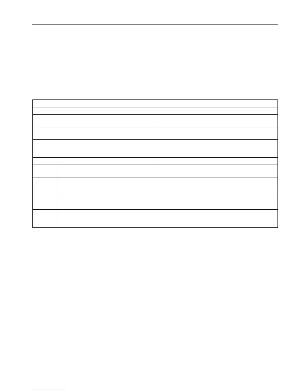
Table 5- 3 Terminal strip -X41
Connection for actuating element at channel 1 "+"
-X41:2 Connected to -X41:1 Connection for actuating element at channel 1 "+", for inter-
connecting Motor Modules in groups
-X41:3 Control of -K41:A2, -K42:A2 , N conductor or
Connection of reference potential for actuating elements at
-X41:4 Connected to -X41:3 Connection of reference potential for actuating elements at
channel 1 and channel 2, for interconnecting Motor Modules
Feedback signal, status -K41, -K42
Connection of supply voltage for optional feedback signal
-X41:6 Feedback signal, status -K41, -K42 Connection for optional checkback signal, for interconnect-
ing Motor Modules in groups
Connection for actuating element at channel 2 "+"
-X41:8 Connected to -X41:7 Connection for actuating element at channel 2 "+", for inter-
connecting Motor Modules in groups
-X41:9 Connection of optional checkback For the option of connecting other checkback signals in
series when Motor Modules are grouped
-X41:10 Output -K41: Permanently wired with
CU320-2: -X132:4 (DI 7)
Output -K41: For connecting to a digital input according to
the Safety settings on the CU320-2 (already wired in option

 Loading...


