Controlling the safety functions
5.3 Control of "STO" and "SS1" via terminals on the Control Unit and the Motor/Power Module
Safety Integrated
78 Function Manual, 07/2016, A5E03264275A
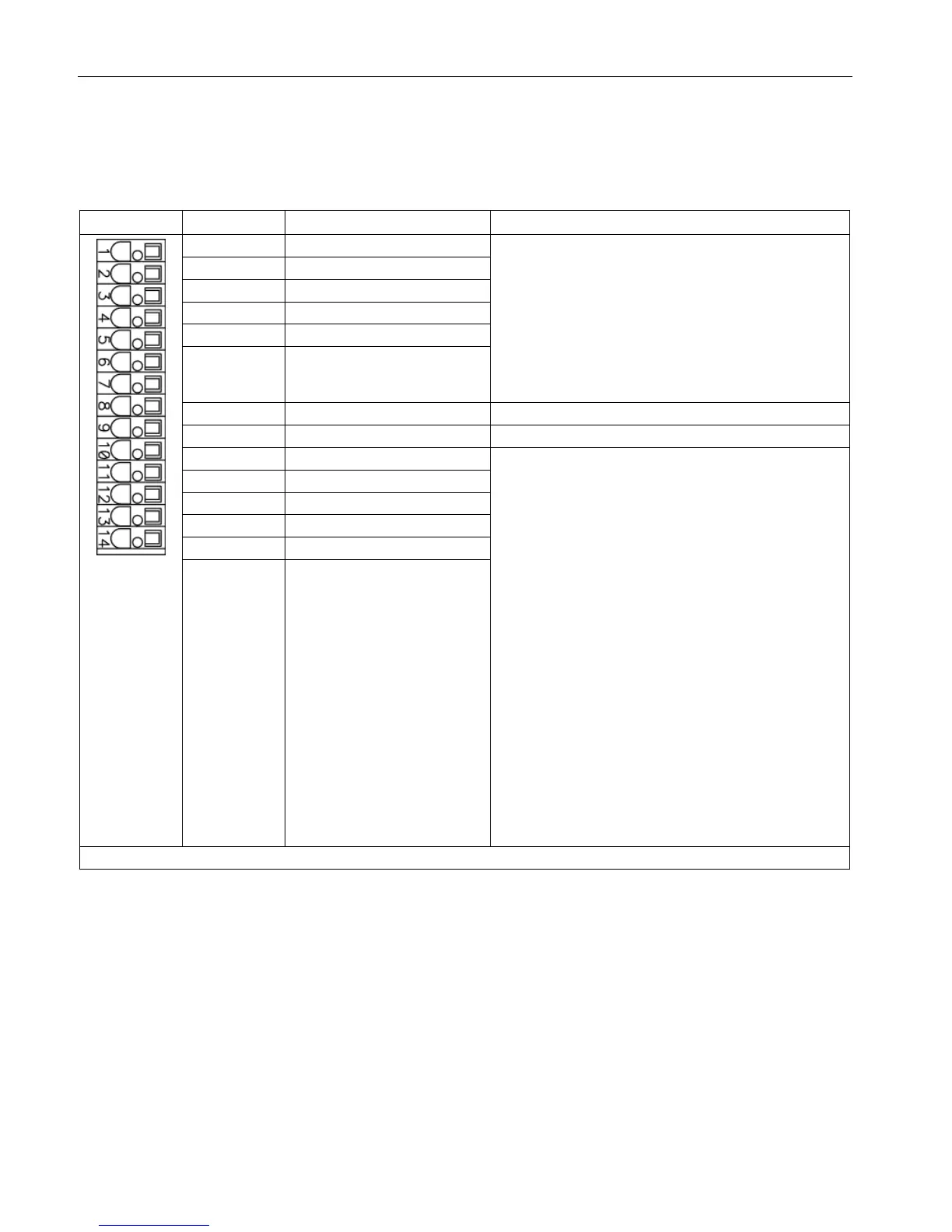
Terminal strip –X132 on the CU320-2 Control Unit
Table 5- 18 Terminal strip –X132 on the CU320-2 Control Unit
Voltage: -30 ... +30 VDC
Typical power consumption: 9 mA at 24 V
Electrical isolation: Reference potential is terminal M2
Level (incl. ripple)
High level: 15 … 30 V
Low-level: -30 … +5 V
Input delay (typ.):
For "0" → "1": 50 μs
Reference potential for terminals 1 ... 6
:
Voltage: -30 ... +30 VDC
Typical power consumption: 9 mA at 24 V
Level (incl. ripple)
High level: 15 … 30 V
Low-level: -30 … +5 V
DI/DO 12, 13, 14, and 15 are "rapid inputs"
2)
Input delay (typ.):
For "0" → "1": 5 μs
For "1" → "0": 50 μs
:
Voltage: 24 V DC
Max. load current per output: 500 mA
Continuous short-circuit proof
Output delay (typ./max.)
3)
:
For "0" → "1": 150 μs / 400 μs
For "1" → "0": 75 μs / 100 μs
Switching frequency:
For resistive load: Max. 100 Hz
For inductive load: Max. 0.5 Hz
For lamp load: Max. 10 Hz
Max. connectable cross-section: 1.5 mm
DI: Digital input; DI/DO: Bidirectional digital input/output; M: Electronics ground; M2: Reference ground
The rapid inputs can be used as probe inputs or as inputs for the external zero mark
3)
Data for: V
cc
= 24 V; Load 48 Ω; High ("1") = 90% V
out
; Low ("0") = 10% V
out

 Loading...


