EasyManuals Logo

Siemens SINAMICS Series Function Manual

Siemens SINAMICS Series
102 pages
To Next Page IconTo Next Page
To Previous Page IconTo Previous Page
Page #92 background imageLoading...
Page #92 background image
Controlling the safety functions
5.4 Activating "SBC" via the Safe Brake Adapter
Safety Integrated
92 Function Manual, 07/2016, A5E03264275A
Interfaces
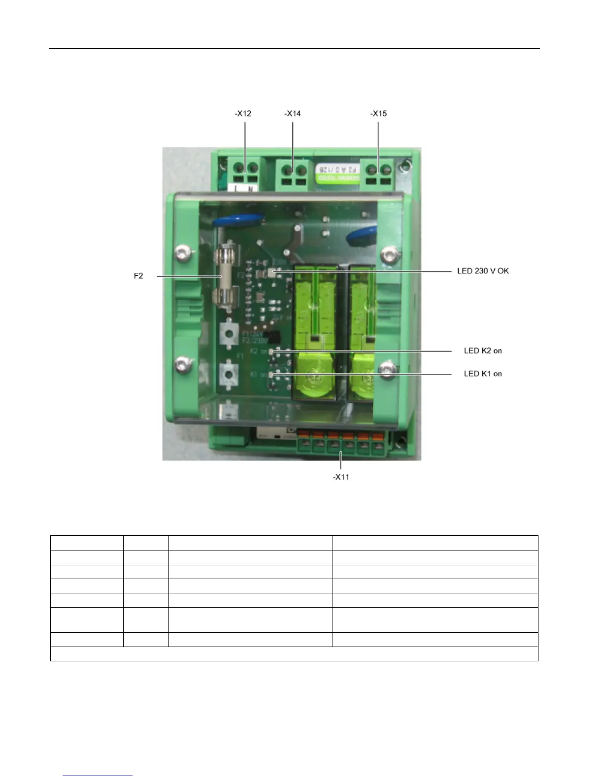
Figure 5-8 Safe Brake Adapter interface overview 230 VAC
Table 5- 25 Terminal block X11, interface to the Control Interface Module
Connection
Signal
Description
Technical data
X11.1
BR+
Control channel 1
Connection to the Control Interface Module, X46:1
X11.2
BR-
Control channel 2
Connection to the Control Interface Module, X46:2
X11.3
FB+
Relay feedback signal
Connection to the Control Interface Module, X46:3
X11.4
FB-
Ground of the relay feedback signal
Connection to the Control Interface Module, X46:4
X11.5 P24 P24 of the auxiliary voltage to supply
the feedback signal
Connection to the Control Interface Module, X42:2
X11.6
M
Ground of the auxiliary voltage
Connection to the Control Interface Module, X42:3
Max. connectable cross-section 2.5 mm
2

Table of Contents

Other manuals for Siemens SINAMICS Series

Questions and Answers:

Question and Answer IconNeed help?

Do you have a question about the Siemens SINAMICS Series and is the answer not in the manual?

Siemens SINAMICS Series Specifications

General IconGeneral
Product LineSINAMICS
Cooling MethodAir-cooled, Liquid-cooled
Voltage Range200 V to 690 V
Power Range0.12kW - 250kW
Communication InterfacesPROFINET, PROFIBUS, Ethernet
Control ModesVector control, V/f control
Protection ClassIP20
TypeVariable Frequency Drives (VFD)

Related product manuals