EasyManuals Logo

Siemens SINAMICS Series Function Manual

Siemens SINAMICS Series
102 pages
To Next Page IconTo Next Page
To Previous Page IconTo Previous Page
Page #94 background imageLoading...
Page #94 background image
Controlling the safety functions
5.4 Activating "SBC" via the Safe Brake Adapter
Safety Integrated
94 Function Manual, 07/2016, A5E03264275A
Table 5- 28 Terminal block X15, fast de-energization
Connection
Signal
Description
X15.1
AUX1
Supply voltage: 230 VAC
Current consumption: 2 A
X15.2 AUX2
Max. connectable cross-section 2.5 mm
2
Spare fuse
The type of spare fuse is as follows: 2 A, time-lag.
Note
Correctly mounting the housing cover after replacing a fuse
An adhesive label is provided on the housing cover indicating the position of the connector.
Mount the cover in the correct position so that the inscription of the label matches the actual
connectors
.
Mounting
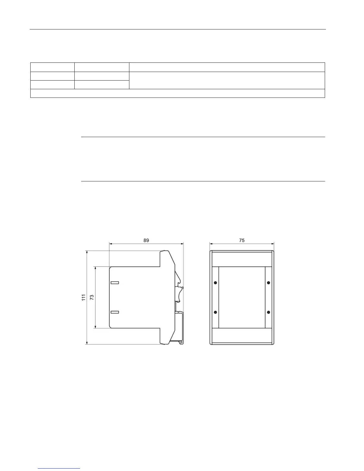
The Safe Brake Adapter is designed for mounting on a rail according to EN 60715
The dimensions are shown in the following dimension drawing.
Figure 5-9 Dimension drawing of the Safe Brake Adapter (data in mm)

Table of Contents

Other manuals for Siemens SINAMICS Series

Questions and Answers:

Question and Answer IconNeed help?

Do you have a question about the Siemens SINAMICS Series and is the answer not in the manual?

Siemens SINAMICS Series Specifications

General IconGeneral
Product LineSINAMICS
Cooling MethodAir-cooled, Liquid-cooled
Voltage Range200 V to 690 V
Power Range0.12kW - 250kW
Communication InterfacesPROFINET, PROFIBUS, Ethernet
Control ModesVector control, V/f control
Protection ClassIP20
TypeVariable Frequency Drives (VFD)

Related product manuals