Parameter list
7.2 Parameter list
SINAMICS V20 Inverter
132 Operating Instructions, 07/2012, A5E03728167
Parameter Function Range Factory
default
Can be
changed
Scaling Data
set
Data
type
Acc.
Level
Note: For best results, it is recommended that auto-detection of Vdc switch-on levels (P1254 = 1) is used.
Setting P1254 = 0 is only recommended when there is a high degree of fluctuation of the DC-link when the
motor is being driven. In this case, ensure the setting of P0210 is correct.
If mains voltage is higher than value entered, automatic deactivation of the Vdc controller may occur to
avoid acceleration of the motor. A warning will be issued in this case (A910).
Default value is depending on inverter type and its rating data.
r0231[0...1] Maximum cable length
[m]
- - - - - U16 3
Indexed parameter to display maximum allowable cable length between inverter and motor.
Index: [0] Maximum allowed unscreened cable length
[1] Maximum allowed screened cable length
Notice: For full EMC compliance, the screened cable must not exceed 25 m in length when an EMC filter is fitted.
P0290 Inverter overload
reaction
0 - 3 2 T - - U16 3
Selects reaction of inverter to an internal thermal overload condition.
0 Reduce output frequency and output current
1 No reduction, trip (F4 / 5/ 6) when thermal limits reached
2 Reduce pulse frequency, output current and output frequency
3 Reduce pulse frequency only and trip (F6) when overload too high
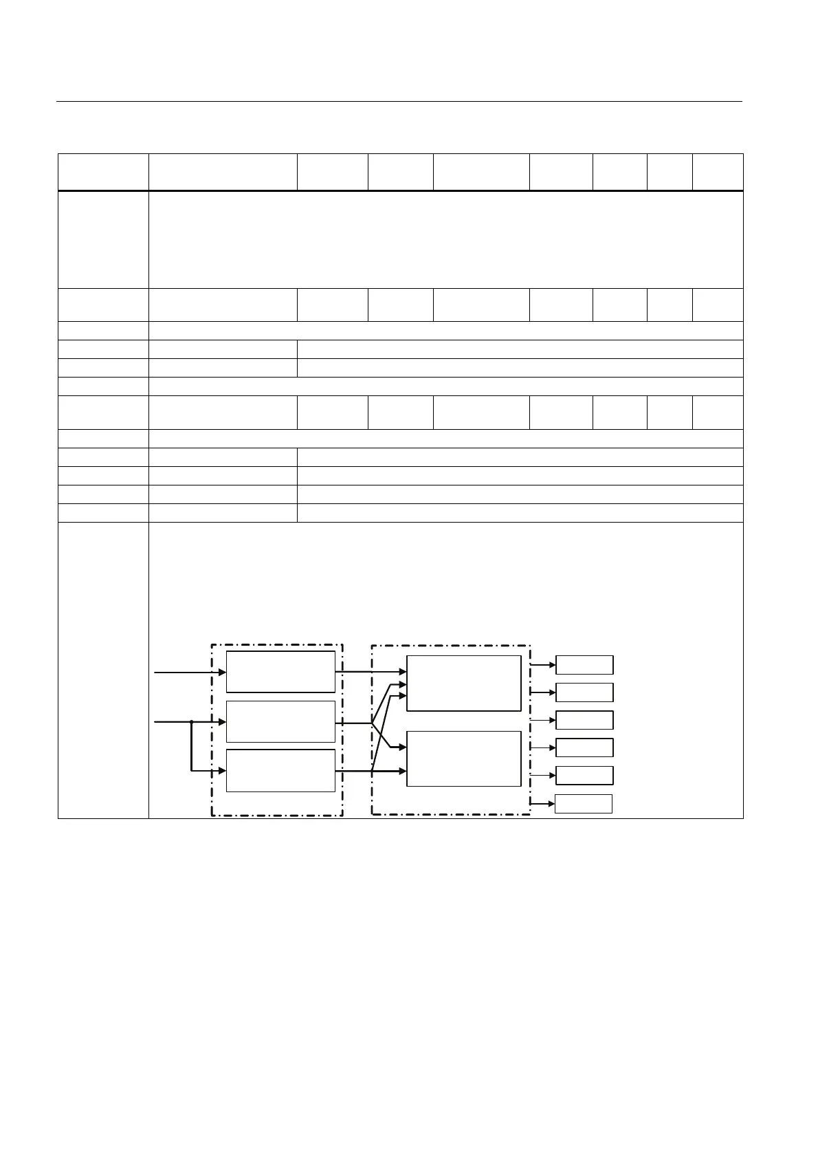
Dependency: Following physical values influence the inverter overload protection (see diagram):
• Heat sink temperature (r0037[0]); causes A504 and F4.
• IGBT Junction temperature (r0037[1]); causes F4 or F6.
• Delta temperature between heat sink and junction temperature; causes A504 and F6.
• Inverter I
2
t (r0036); causes A505 and F5.
+HDWVLQNWHPSHUDWXUH
,QYHUWHURYHUORDGUHDFWLRQ
,QYHUWHUPRQLWRULQJ
LBPD[FRQWURO
IBSXOVHFRQWURO
,*%7WHPSHUDWXUH
3
3
3
3
U
U
I
2
t
$
$
$
)
)
)

 Loading...


