Parameter list
7.2 Parameter list
SINAMICS V20 Inverter
Operating Instructions, 07/2012, A5E03728167
131
Parameter Function Range Factory
default
Can be
changed
Scaling Data
set
Data
type
Acc.
Level
[1] Not used
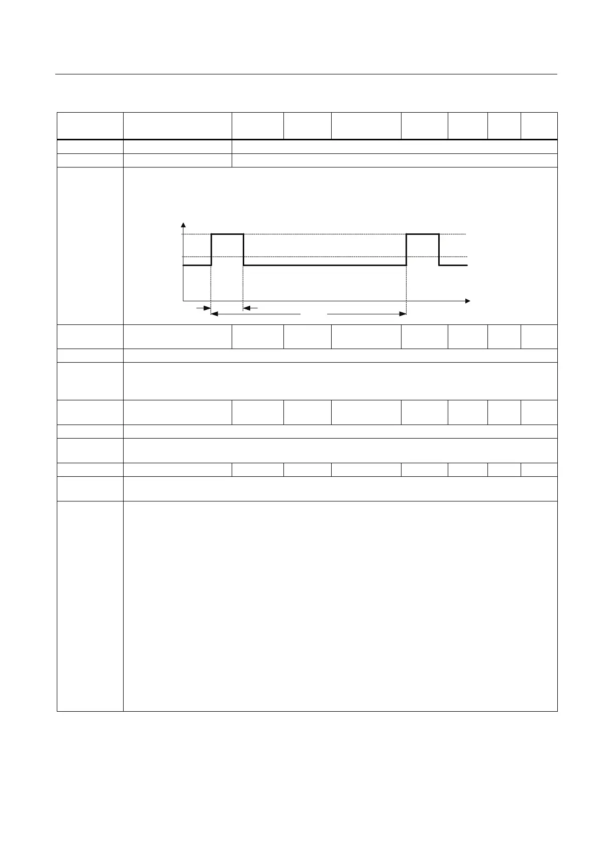
[2] Rated high overload (HO) current
Note: The rated high overload (HO) current r0207[2] values correspond to suitable 4-pole Siemens standard
motors (IEC) for the selected load cycle (see diagram). r0207[2] is the default value of P0305 in
association with the HO application (load cycle).
,QYHUWHUFXUUHQWSRZHU
5DWHGLQYHUWHUFXUUHQWFRQWLQXRXV
%DVHORDGFXUUHQWZLWKRYHUORDGFDSDELOLW\
6KRUWWLPHFXUUHQW
U
U>@
V
V
W
r0208 Rated inverter voltage
[V]
- - - - - U32 2
Displays nominal AC supply voltage of inverter.
Note: r0208 = 230: 200 - 240 V + / - 10 %
r0208 = 400: 380 - 480 V + / - 10 %
r0208 = 575: 500 - 600 V + / - 10 %
r0209 Maximum inverter
current [A]
- - - - - Float 2
Displays maximum output current of inverter.
Dependency: r0209 depends on the derating which is affected by pulse frequency P1800, ambient temperature and
altitude. The data of deration is given in the Operating Instructions.
P0210 Supply voltage [V] 0 - 1000 400 T - - U16 3
P0210 defines the supply voltage. Its default value depends upon the type of inverter. If P0210 does not
correspond to the supply voltage, then it must be modified.
Dependency: Optimizes Vdc controller, which extends the ramp-down time if regenerative energy from motor would
otherwise cause DC-link overvoltage trips.
Reducing the value enables controller to cut in earlier and reduce the risk of overvoltage.
Set P1254 ("Auto detect Vdc switch-on levels") = 0. Cut-in levels for Vdc controller and compound braking
are then derived directly from P0210 (supply voltage):
• Vdc_min switch-on level (r1246) = P1245 * sqrt(2) * P0210
• Vdc_max switch-on level (r1242) = 1.15 * sqrt(2) * P0210
• Dynamic braking switch-on level = 1.13 * sqrt(2) * P0210
• Compound braking switch-on level = 1.13 * sqrt(2) * P0210
Set P1254 ("Auto detect Vdc switch-on levels") = 1. Cut-in levels for Vdc controller and compound braking
are then derived from r0070 (DC-link voltage):
• Vdc_min switch-on level (r1246) = P1245 * r0070
• Vdc_max switch-on level (r1242) = 1.15 * r0070
• Dynamic braking switch-on level = 0.98 * r1242
• Compound braking switch-on level = 0.98 * r1242
Auto-detection calculations are only performed when the inverter has been in standby for over 20s. When
pulses are enabled, the calculated values are frozen until 20s after pulses cease.

 Loading...


