Parameter list
7.2 Parameter list
SINAMICS V20 Inverter
Operating Instructions, 07/2012, A5E03728167
145
Parameter Function Range Factory
default
Can be
changed
Scaling Data
set
Data
type
Acc.
Level
Bit Signal name 1 signal 0 signal
00 Digital input 1 Yes No
01 Digital input 2 Yes No
02 Digital input 3 Yes No
03 Digital input 4 Yes No
11 Analog input 1 Yes No
12 Analog input 2 Yes No
Note: Segment is lit when signal is active.
P0724 Debounce time for digital
inputs
0 - 3 3 T - - U16 3
Defines debounce time (filtering time) used for digital inputs.
0 No debounce time
1 2.5 ms debounce time
2 8.2 ms debounce time
3 12.3 ms debounce time
P0727[0...2] Selection of 2 / 3-wire
method
0 - 3 0 C(1), T - CDS U16 2
Determines the control method using the terminals. This parameter allows the selection of the control
philosophy. The control philosophies exclude each other.
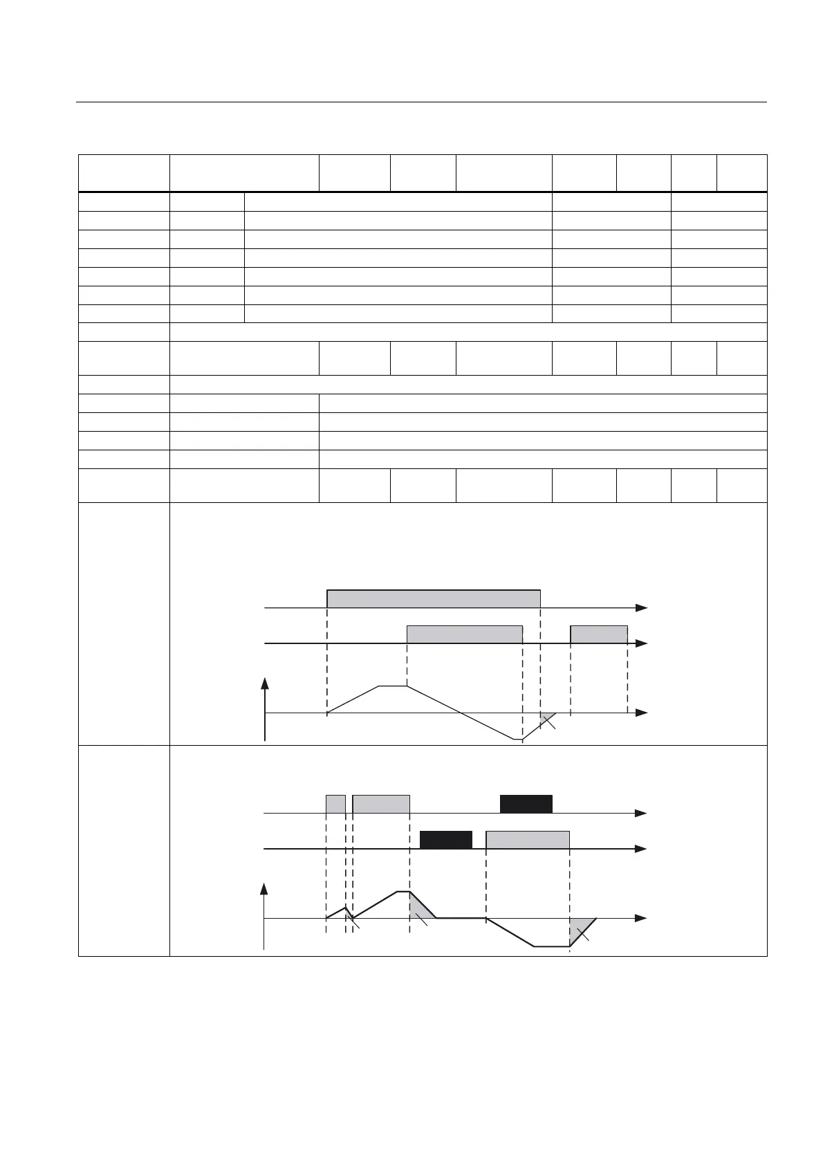
2 / 3-wire control allows to start, stop and reverse the inverter in one of the following ways:
• 2-wire control with Siemens standard control
using ON / OFF1 and REV as permanent signals
&RQWURO
FRPPDQGV
IBRXW
W
2))
212))
5(9
• 2-wire control with Siemens standard control
using ON / OFF1 and ON_REV / OFF1 as permanent signals
&RQWURO
FRPPDQGV
&RPPDQGLJQRUHG
&RPPDQGLJQRUHG
IBRXW
W
2))
2))
2))
212))
21B5(9
2))

 Loading...


