Parameter list
7.2 Parameter list
SINAMICS V20 Inverter
174 Operating Instructions, 07/2012, A5E03728167
Parameter Function Range Factory
default
Can be
changed
Scaling Data
set
Data
type
Acc.
Level
Dependency: Compound braking depends on the DC link voltage only (see threshold above). This will happen on OFF1,
OFF3 and any regenerative condition. It is disabled, when:
• DC braking is active
• Flying start is active
Notice: Increasing the value will generally improve braking performance; however, if you set the value too high, an
overcurrent trip may result.
If used with dynamic braking enabled as well compound braking will take priority.
If used with the Vdc_max controller enabled the inverter behavior when braking may be worsened
particularly with high values of compound braking.
Note: P1236 = 0 means that compound braking is not activated.
P1237 Dynamic braking 0 - 5 0 U, T - - U16 2
Dynamic braking absorbs the braking energy in a chopper resistor.
This parameter defines the rated duty cycle of the braking resistor (chopper resistor).
Dynamic braking is active when the function is enabled and DC-link voltage exceeds the dynamic braking
switch-on level.
Dynamic braking switch-on level (V_DC,Chopper) :
If P1254 = 0 --> V_DC,Chopper = 1.13 * sqrt(2) * V_mains = 1.13 * sqrt(2) * P0210
otherwise V_DC,Chopper = 0.98 * r1242
0 Disabled
1 5 % duty cycle
2 10 % duty cycle
3 20 % duty cycle
4 50 % duty cycle
5 100 % duty cycle
Note: This parameter is only applicable for inverters of frame size D. For frame sizes A to C, the duty cycle of the
braking resistor can be selected with the dynamic braking module (see Appendix "
Dynamic braking
module (Page 257)").
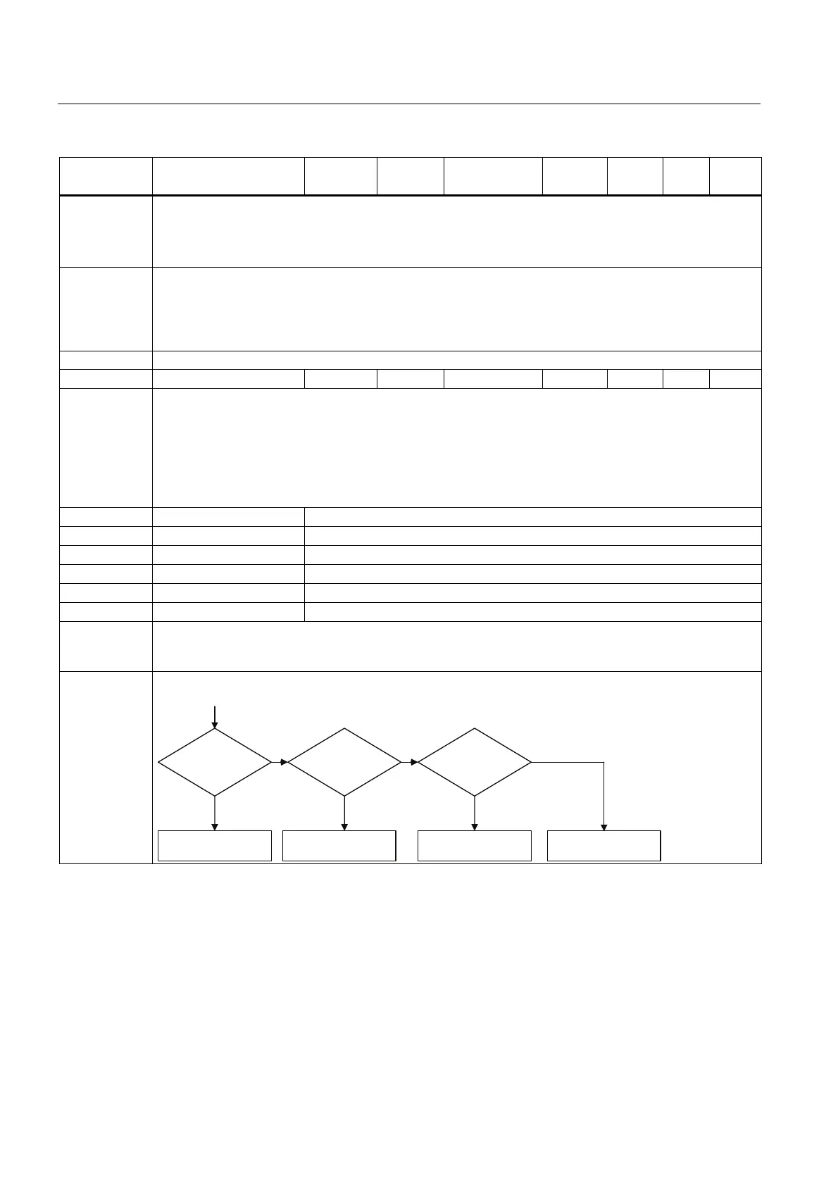
Dependency: If dynamic braking is used with DC braking enabled as well as compound braking, DC braking and
compound braking will take priority.
'&EUDNLQJ
'&EUDNLQJ
HQDEOHG
&RPSRXQGEUDNLQJ
HQDEOHG
'\QDPLFEUDNLQJ
HQDEOHG
&RPSRXQG
EUDNLQJ
'\QDPLF
EUDNLQJ
QR
\HV \HV \HV
QR
QR
'LVDEOHG
3!
"
3!
"
3!
"

 Loading...


