Parameter list
7.2 Parameter list
SINAMICS V20 Inverter
Operating Instructions, 07/2012, A5E03728167
175
Parameter Function Range Factory
default
Can be
changed
Scaling Data
set
Data
type
Acc.
Level
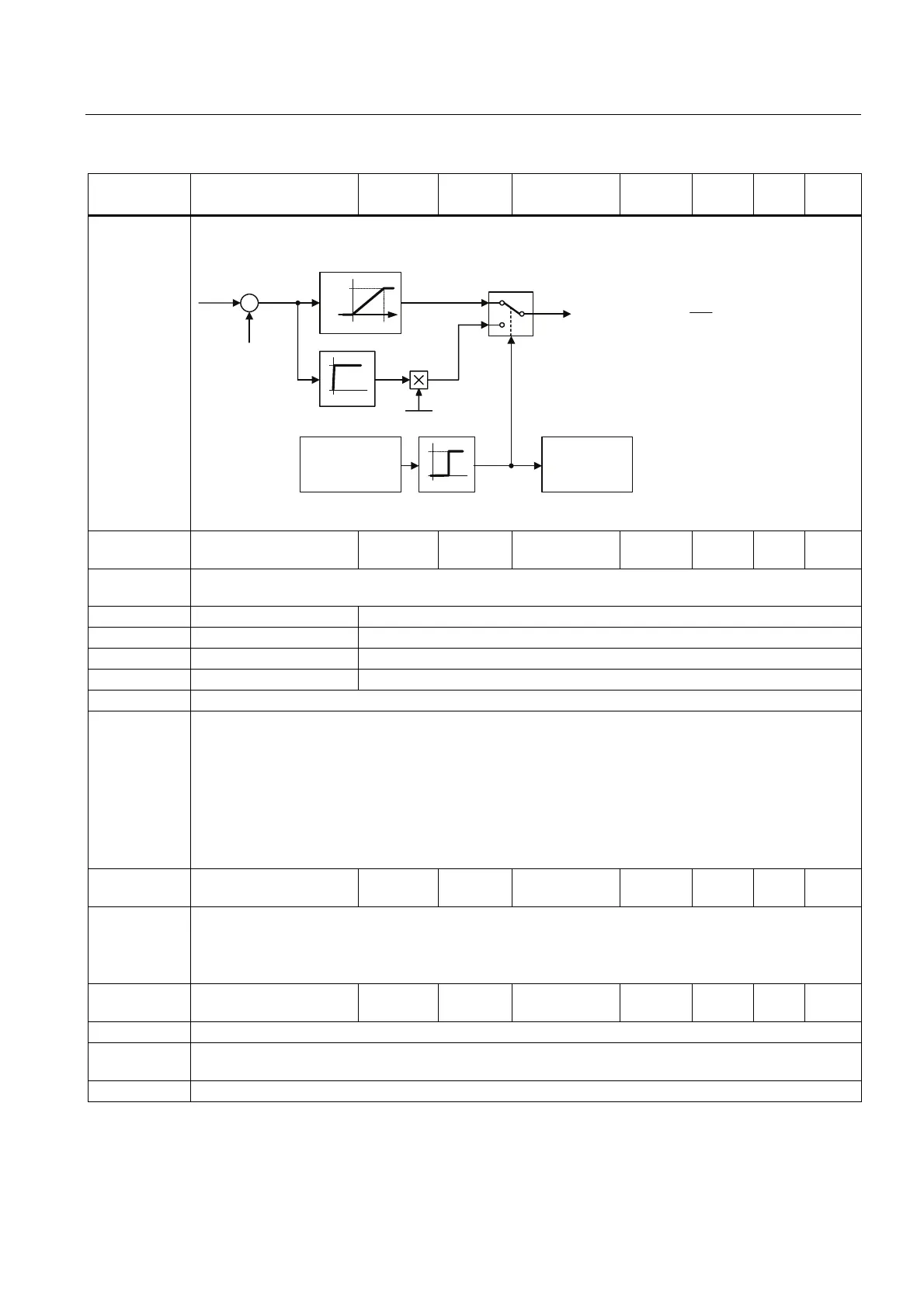
Notice: Initially the brake will operate at a high duty cycle dependant on the DC link level until the thermal limit is
approached. The duty cycle specified by this parameter will then be imposed. The resistor should be able
to operate at this level indefinitely without overheating.
'XW\F\FOH
PRQLWRULQJ
$ODUP$
[
ຘ
ದ
9
W
W
9
9
'&DFW
'&&KRSSHU
&KRSSHU21
&KRSSHU
˂9
[
˂9 9IRU9
3
The threshold for the warning A535 is equivalent to 10 seconds running at 95 % duty cycle. The duty cycle
will be limited when it was running 12 seconds at 95 % duty cycle.
P1240[0...2] Configuration of Vdc
controller
0 - 3 1 C, T - DDS U16 3
Enables / disables Vdc controller. The Vdc controller dynamically controls the DC link voltage to prevent
overvoltage trips on high inertia systems.
0 Vdc controller disabled
1 Vdc_max controller enabled
2 Kinetic buffering (Vdc_min controller) enabled
3 Vdc_max controller and kinetic buffering (KIB) enabled
Caution: If P1245 increased too much, it may interfere with the inverter normal operation.
Note:
• Vdc_max controller:
Vdc_max controller automatically increases ramp-down times to keep the DC-link voltage (r0026)
within limits (r1242).
• Vdc_min controller:
Vdc_min is activated if DC-link voltage falls below the switch on level P1245. The kinetic energy of the
motor is then used to buffer the DC-link voltage, thus causing deceleration of the inverter. If the inverter
trips with F3 immediately, try increasing the dynamic factor P1247 first. If still tripping with F3 try then
increasing the switch on level P1245.
r1242 CO: Switch-on level of
Vdc_max [V]
- - - - - Float 3
Displays switch-on level of Vdc_max controller.
Following equation is only valid, if P1254 = 0:
r1242 = 1.15 * sqrt(2) * V_mains = 1.15 * sqrt(2) * P0210
otherwise r1242 is internally calculated.
P1243[0...2] Dynamic factor of
Vdc_max [%]
10 - 200 100 U, T - DDS U16 3
Defines dynamic factor for DC link controller.
Dependency: P1243 = 100 % means P1250, P1251 and P1252 (gain, integration time and differential time) are used as
set. Otherwise, these are multiplied by P1243 (dynamic factor of Vdc_max).
Note: Vdc controller adjustment is calculated automatically from motor and inverter data.

 Loading...


