Parameter list
7.2 Parameter list
SINAMICS V20 Inverter
Operating Instructions, 07/2012, A5E03728167
209
Parameter Function Range Factory
default
Can be
changed
Scaling Data
set
Data
type
Acc.
Level
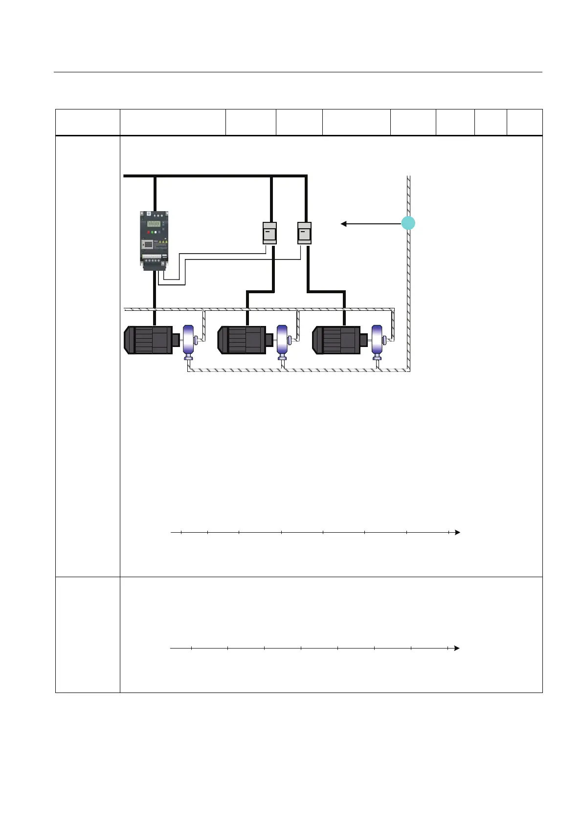
The diagram below shows a typical pumping system.
A similar system could be set up using fans and air ducts, instead of pumps and pipes.
0DLQV
,QYHUWHU
0RWRUVWDUWHUV
3UHVVXUHVHQVRU
7RLQYHUWHU3,'LQSXW
09 0 0
By default the motor states are controlled from digital outputs (DO).
In the text below, the following terminology will be used:
MV - Variable speed (Inverter controlled motor)
M1 - Motor switched with digital output 1 (DO1)
M2 - Motor switched with digital output 2 (DO2)
Staging: The process of starting one of the fixed speed motors.
De-staging: The process of stopping one of the fixed speed motors.
When the inverter is running at maximum frequency, and the PID feedback indicates that a higher speed is
required, the inverter switches on (stages) one of the digital output controlled motors M1 and M2.
At the same time, to keep the controlled variable as constant as possible, the inverter must ramp down to
minimum frequency.
Therefore, during the staging process, PID control must be suspended (see P2378 and diagram below).
P2371 = 0
1
2
3
--------
-M1M1M1M1M1M1M1
- M1 M1+M2 M1+M2 M1+M2 M1+M2 M1+M2 M1+M2
- M1 M2 M1+M2 M1+M2 M1+M2 M1+M2 M1+M2
t
1. 2. 3. 4. 5. 6. 7.
Staging of external motors (M1, M2)
6ZLWFKRQ
When the inverter is running at minimum frequency, and the PID feedback indicates that a lower speed is
required, the inverter switches off (de-stages) one of the digital output controlled motors M1 and M2.
In this case, the inverter must ramp from minimum frequency to maximum frequency outside of PID control
(see P2378 and diagram below).
P2371 = 0
1
2
3
--------
M1-------
M1+M2M1------
M1+M2 M2 M1 - - - - -
t
1. 2. 3. 4. 5. 6. 7.
Destaging of external motors (M1, M2)
6ZLWFKRII

 Loading...


