Parameter list
7.2 Parameter list
SINAMICS V20 Inverter
208 Operating Instructions, 07/2012, A5E03728167
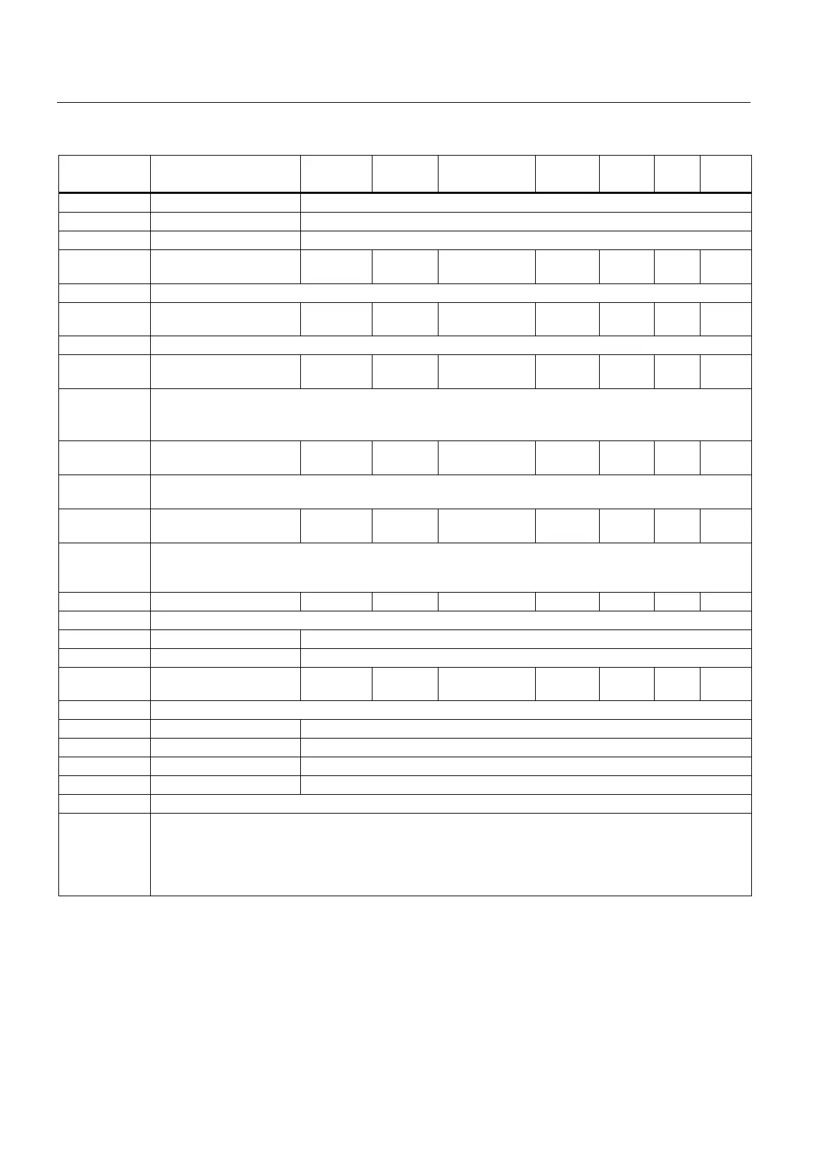
Parameter Function Range Factory
default
Can be
changed
Scaling Data
set
Data
type
Acc.
Level
0 Disable
1 Fault
2 Warn
P2361[0...2] Cavitation threshold [%] 0.00 -
200.00
40.00 U, T - DDS Float 2
Feedback threshold over which a fault / warning is triggered, as a percentage (%).
P2362[0...2] Cavitation protection
time [s]
0 - 65000 30 U, T - DDS U16 2
The time for which cavitation conditions have to be present before a fault / warning is triggered.
P2365[0...2] Hibernation enable /
disable
0 - 1 0 U, T - DDS U16 2
Enable or disable the hibernation functionality.
0 = disabled
1 = enabled
P2366[0...2] Delay before stopping
motor [s]
0 - 254 5 U, T - DDS U16 3
With hibernation enabled. If the frequency demand drops below the threshold there is a delay of P2366
seconds before the inverter is stopped.
P2367[0...2] Delay before starting
motor [s]
0 - 254 2 U, T - DDS U16 3
With hibernation enabled. If pulses have been disabled by the unit going into hibernation, and the
frequency demand has increased to above the hibernation threshold, there will be a delay of P2367
seconds before the inverter restarts.
P2370[0...2] Motor staging stop mode 0 - 1 0 T - DDS U16 3
Selects stop mode for external motors when motor staging is in use.
0 Normal stop
1 Sequence stop
P2371[0...2] Motor staging
configuration
0 - 3 0 T - DDS U16 3
Selects configuration of external motors (M1, M2) used for motor staging feature.
0 Motor staging disabled
1 M1 = 1 x MV, M2 = Not fitted
2 M1 = 1 x MV, M2 = 1 x MV
3 M1 = 1 x MV, M2 = 2 x MV
Caution: For this kind of motor application it is mandatory to disable negative frequency setpoint!
Note: Motor staging allows the control of up to 2 additional staged pumps or fans, based on a PID control
system.
The complete system consists of one pump controlled by the inverter with up to 2 further pumps / fans
controlled from contactors or motor starters.
The contactors or motor starter are controlled by outputs from the inverter.

 Loading...


